Build the wing – Top Flite TOPA0145 User Manual
Page 25
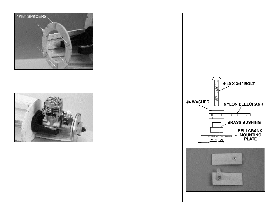
❏ 45. Glue the other half of the nose ring (NR) in
position on the front of the fuselage. Temporarily glue
a few 1/16" [1.6mm] spacers to the nose ring to act
as spacers for the spinner.
❏ 46. Position the engine in place on the engine
mount. With the spinner backplate centered on the
nose ring, tack glue the spinner backplate to the
1/16" [1.6mm] spacers. Lock the spinner backplate in
place with the prop nut. This now shows the exact
position for mounting the engine.
❏ 47. Mark the location of the mounting holes on
the mount. Remove the engine but leave the spinner
backplate glued to the nose ring spacers. Drill a #29
hole ( a 1/8" [3.2mm] bit will be close if you don't have
a set of number bits) and tap the mount with a 8-32 tap.
Hint: The Great Planes Dead Center
™
Tool works
great for this!
❏ 48. Install the engine onto the engine mount and
put the prop nut back on the engine to hold the
spinner backplate tight to the nose ring spacers.
❏ 49. Locate the piece of 3/32" x 2 3/4" [2.4 x 70mm]
balsa sheet that was left over from sheeting the
fuselage on page 16, step 20. Glue it in position from
F2 to the nose ring.
❏ 50. Leave the engine and spinner backplate
mounted in place throughout the entire sheeting of
the fuselage. This will assure you that the nose ring
and spinner backplate will be properly aligned when
the sheeting is glued in place. Some of the
photographs shown in the manual do not show the
engine and spinner backplate mounted. We removed
them for clarity in the instructions, but be sure to
leave the engine and spinner in place as you
continue building.
Hint: When you complete the entire fuselage
construction and sheeting, wet the fuselage sheeting
from F2 forward to the nose ring and let it dry
overnight. After the wood has dried you can break
the spinner backplate away from the nose ring and
the temporary shims.
❏ 51. At this point you must install the pushrod for the
elevator. After we get the fuselage closed you will no
longer have access to the clevis. Make sure when
installing the clevis that you have a piece of tubing
over it to keep it locked in position. You may also
install the rudder and throttle connections at this time.
Set the fuselage aside and get started on the wing.
Don't be concerned that we still have some work
remaining on the fuselage, it will be helpful to leave
it open until the wing is all mounted.
BUILD THE WING
NOTE: The wing panels are built "UPSIDE-DOWN"
on the plan. Since it is the standard procedure to
show the Top View of the wing and the wing
panels are built upside-down, the LEFT wing
panel is built over the RIGHT Wing Top View and
vice-versa. This does not present any problems -
just be sure to build a left and a right wing.
❏ 1. Locate the four 1/4" x 3/8" x 36" [6.4 x 9.5 x
914mm] basswood Wing Spars, then cut them so they
are 1/2" [12.7mm] longer than shown on the plan. Save
the cut-off ends for the flap servo hatch mounts.
❏ 2. Perform this step only if you are going to be
installing flaps. Drill 1/8" [3.2mm] holes through the
4-40
BLIND
NUT
25