Top Flite TOPA0145 User Manual
Page 13
❏ 12. Using the sketch above, cut six hinges from
the CA hinge strip supplied with this kit. Snip the
corners off so they go into the slots easier. You may
cut all the hinges now, or cut them as you need them.
❏ ❏ 13. Test fit the hinges into the slots. If the hinges
do not slide into the slots easily, work your knife
blade back and forth in the slot a few times to provide
more clearance (it is really the back edge of the
blade that does the work here in widening the slot).
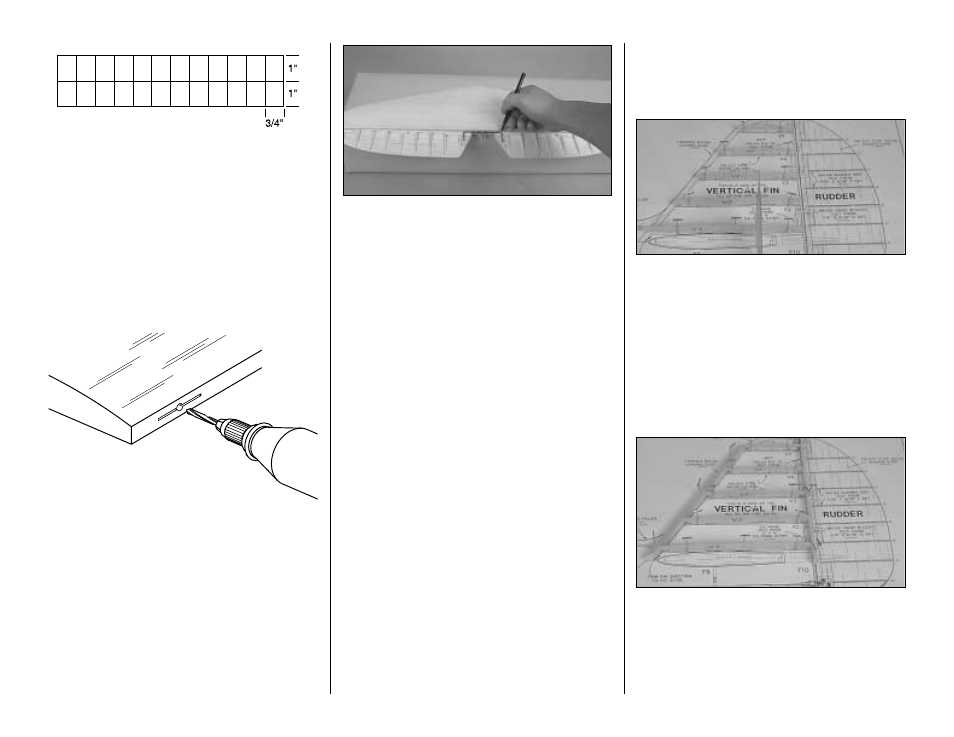
❏ ❏ 14. Drill a 3/32" [2.4mm] hole, 1/2" [12.7mm]
deep in the center of the hinge slots. Use a rotary
tool with a 3/32" [2.4mm] drill bit or a carbide cutter
for the best results. Reinsert your knife blade to
clean out the slot after you drill the holes.
❏ ❏ 15. Test fit the elevator to the stab with the
hinges. If any hinge slots are not wide enough or are
misaligned, make adjustments so the elevators
accurately fit the stab.
Return to Step 1 and build the other elevator.
❏ 16. Determine which side of the stab looks the
best. Designate that side as the top. Use a file or a
rotary tool with a cut-off wheel to remove sharp
edges or burrs on the ends of the elevator joiner
wire. Place the horizontal Stab and elevators over
the plan and position the elevator joiner wire on the
top of the elevators in the location shown. Mark the
leading edge of the elevators where the arm portion
of the joiner wire will enter as shown on the plan.
❏ 17. Drill a 9/64" (or 1/8") [3.6mm] hole at the marks
you made on the centerline of both elevator leading
edges for the joiner wire. Cut a groove in the
leading edge of both elevators to accommodate the
joiner wire.
Hint: Use a 5/32" [4mm] brass tube sharpened at
one end to cut the grooves.
❏ 18. Bevel the leading edges of the elevators to a
"V" as shown in the cross section on the plan. Use
the centerline on the elevator leading edges as a
guide. Test fit the elevators to the stab with the joiner
wire and the hinges. Note that the horn on the joiner
wire points downward. Cut a small notch in the TE of
the stab for the horn on the joiner wire. If necessary,
remove the joiner and tweak it so both elevators are
in the same plane.
❏ 19. Once more, test fit the elevators to the stab
with the hinges and the joiner wire. Make sure you
can obtain the control throws indicated on page 43 of
the manual. If you cannot, increase the "V" on the
leading edge of the elevators.
Set the stab and elevators aside.
Build the fin and rudder
❏ 1. Tape the fuse plan to your building board. Cover
the fin and rudder portion of the plan with Plan Protector.
❏ 2. Pin balsa fin ribs V1 through V5 to the plan
using T-pins as shown in the photograph. Check that
the fin ribs are perpendicular to the building board
using a triangle or square.
❏ 3. Carefully bevel the front of the ribs to
accommodate the sweep of the tapered LE stick.
❏ 4. Cut the balsa leading edge from a 5/16" x 15"
[7.9 x 381mm] tapered balsa leading edge. Cut it to
the length shown on the plan.
❏ 5. Pin the balsa leading edge stick and the die-cut
1/8” balsa fin TE spar to the plan in the same manner
as the ribs in step 2. Be sure to align the top of the fin
LE with the tops of the ribs, allowing the excess to
protrude below the ribs (to be trimmed later). Do the
same with the fin TE spar. Once you are satisfied with
the fit, glue the ribs to the LE and TE.
DRILL A 3/32" HOLE
1/2" DEEP, IN CENTER
OF HINGE SLOT
13