Index, Keep all booklets for future reference, 0 troubleshooting (cont'd) – Reznor MAPSII Series REDA Users Manual User Manual
Page 28
Form O-MAPS II, P/N 209179 R7, Page 28
Record installation information on the back
of the installation manual, Form I-MAPS II.
Keep ALL booklets for future reference.
www.RezSpec.com; (800) 695-1901
©2008 Thomas & Betts, All rights reserved.
Trademark Note: Reznor
®
and MAPS
®
are registered in the United States.
9/08 Form O-MAPS II (Version B.3)
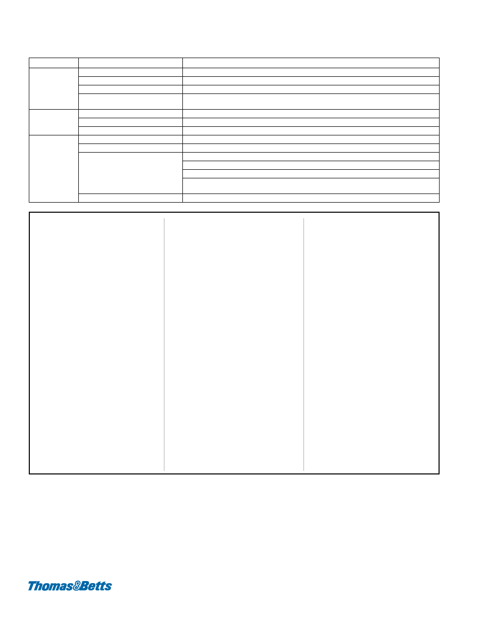
Troubleshooting the Electric Heat Section - Models REDA and RECA
11.0 Troubleshooting (cont'd)
PROBLEM
PROBABLE CAUSE
REMEDY
Unit does not
operate
1. No power to unit
1. Turn on power; check supply fuses or main circuit breaker.
2. Blown fuses
2. Check and replace if necessary.
3. Defective or incorrect wiring.
3. Check wiring and connections. Refer to wiring diagram provided with unit.
4. Defective or burned out control
transformer
4. Check secondary voltage with voltmeter. Replace if necessary.
Fan operates but
element does
not heat
1. Dirty filters
1. Check filters and clean or replace if necessary.
2. Defective air proving switch
2. Check and replace if necessary.
3. Blown element fuses
3. Check and replace element fuses if necessary.
Insufficient heat 1. Burned out element
1. Turn off power and check element resistance with ohmmeter. Replace if open.
2. Blown fuses
2. Check and replace if necessary.
3. Cycling on limit control
3.
a) Check air throughput (temperature rise).
b) Check motor rpm against nameplate rating. Replace motor if speed is too slow.
c) Defective limit control. Check wiring and connections. Check continuity through control and
replace if necessary.
4. Defective or incorrect wiring.
4. Check wiring and connections. Refer to wiring diagram provided with unit.
Index
B
Belt 7
Brazing 15
Burner Maintenance 21
Burner Orifices 22
Burner Removal Instructions 21
C
Charge the System 17
Coil Maintenance 8
Combustion Air Pressure Switch 24
Condenser Coil Connections 8
Cross-Reference by Model/Size and
Curb duct furnace 21
D
DSI Integrated Control Module 22
Duct furnace 21
E
Electric Heat Section Maintenance 25
Evacuate the System 16
Evaporative Coils 8
F
Filters in the Outside Air Hood 6
G
Gas Heat Section Maintenance 20
Gas Valves 24
GENERAL 2
H
Hazard Intensity Levels 3
I
Ignition System 22
Ignitor 23
Inlet Air Filters 6
L
Lights on the DSI Integrated Control
Limit Control 24
Locations of Standard and Optional
M
Maintenance Schedule 3
O
Outside Air Hood 7
R
Re-Heat Pump 10
Refrigerant Temperatures 10
S
Signal Conditioner 24
Superheat 18
System Startup 18
T
Thermal Expansion Valves 20
Troubleshooting - Gas Heat Section
Troubleshooting Gas Heat Section 26
Troubleshooting the Electric Heat Sec-
tion 28
V