0 gas heat maintenance (cont'd) – Reznor MAPSII Series REDA Users Manual User Manual
Page 22
Form O-MAPS II, P/N 209179 R7, Page 22
����������������������
����������
�����������
���������������������
�����������������������
�������
��������
�����
�����������
����������
�����������
�����������
����
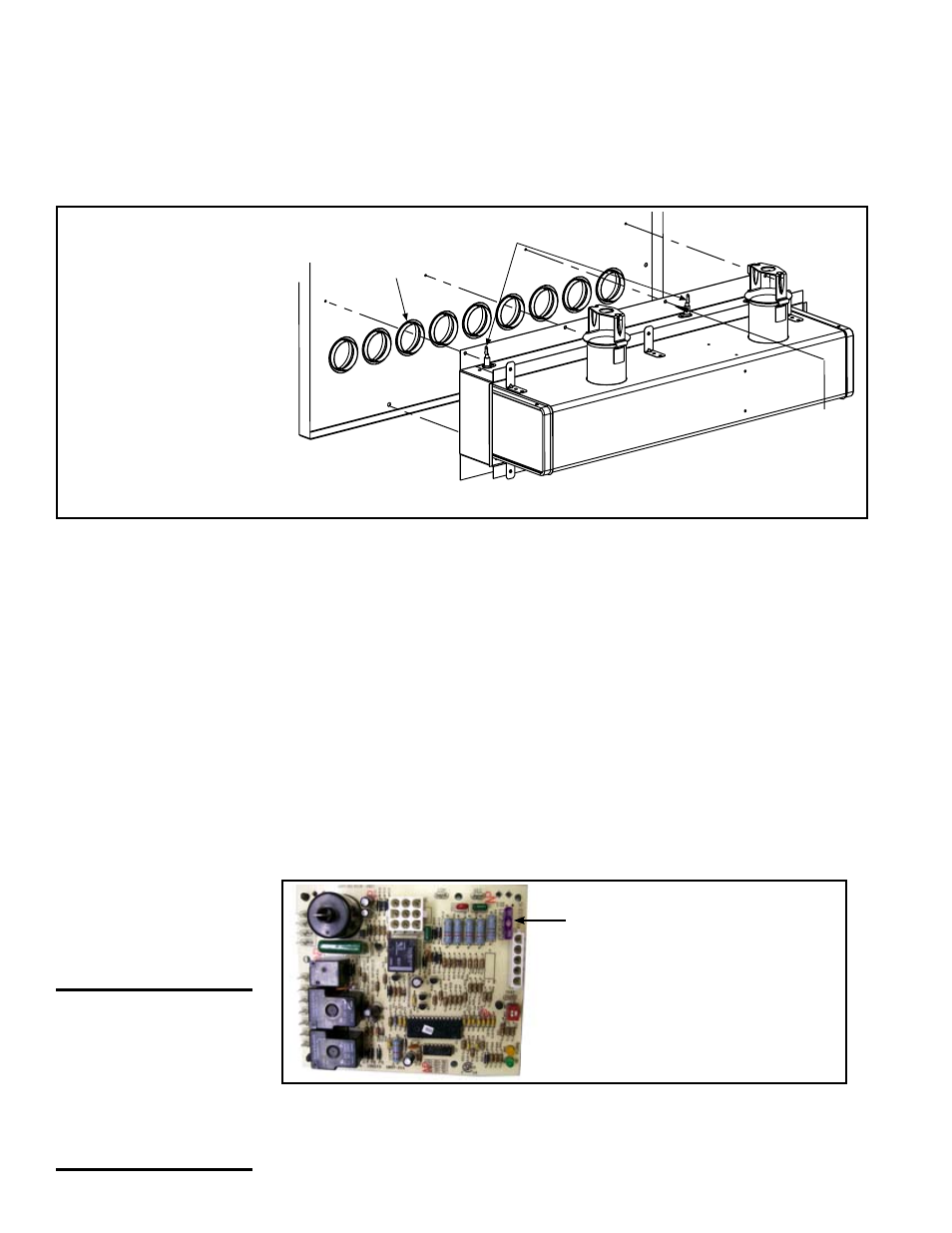
FIGURE 12B -
Remove the Burner
Assembly
(Venter motor and
gas train are already
removed in this
illustration.)
Inspect the Lower
Portion of the Heat
Exchanger (with
burner assembly
removed)
Inspect and Clean the Burner (cont'd)
9.0 Gas Heat
Maintenance
(cont'd)
Burner Orifices
Burner orifices usually only need to be replaced when converting gas from
natural to propane or propane to natural. If ordering a replacement orifice only,
give BTUH content and specific gravity of gas, as well as the model and serial
number of the unit and the orifice size. Each burner has two venturi and each
venturi takes a different size of orifice. When removing or replacing the burner
orifices be careful not to damage the venturi tubes and/or the brackets.
Ignition System
DSI Integrated Control Module (ignition system circuit board) - See FIG-
URE 13. The module monitors the operation of the gas heater including igni-
tion. The only replaceable component is the 3 amp Type ATC or ATO fuse. If
the fuse is blown, the problem is most likely an external overload. Correct the
problem and replace the fuse.
Do not attempt to disassemble the control module. However, each heating sea-
son check the lead wires for insulation deterioration and good connections.
Proper operation of the direct spark ignition system requires a minimum flame
signal of 1.0 microamps as measured by a microampmeter.
CAUTION: Due to
high voltage on
the spark wire and
electrode, do not
touch when ener-
gized. See Hazard
Levels, page 3.
FIGURE 13 - DSI
Integrated Control
Module (Ignition
System Circuit
Board)
Only replaceable part
is a Type ATC or ATO 3
amp fuse (Color Code
Violet), P/N 201685.
dirty, remove both of the burner end caps. Remove the screws that hold the
end caps to the burner housing. Lightly tap end caps to remove.
Clean all foreign material from the burner and venturi. After the burner is thor-
oughly cleaned, replace the end caps making certain that they are tight against
the burner housing.
NOTE: If any of the burner components are damaged or
deteriorated, replace the burner assembly.
At the burner flame entrance of each tube, shine a bright light into each heat
exchanger section. With the light shining into the heat exchanger, observe the
outside for visible light. (The outside of the heat exchanger is visible with the
blower door open and the blower mounting plate slid out.) Repeat this proce-
dure with each heat exchanger section. If any light is observed, replace the
heat exchanger.