Burner maintenance – Reznor MAPSII Series REDA Users Manual User Manual
Page 21
Form RZ-NA O-MAPS II, P/N 209179 R7, Page 21
Gas-fired Heat Exchanger Maintenance
Burner Removal
Instructions
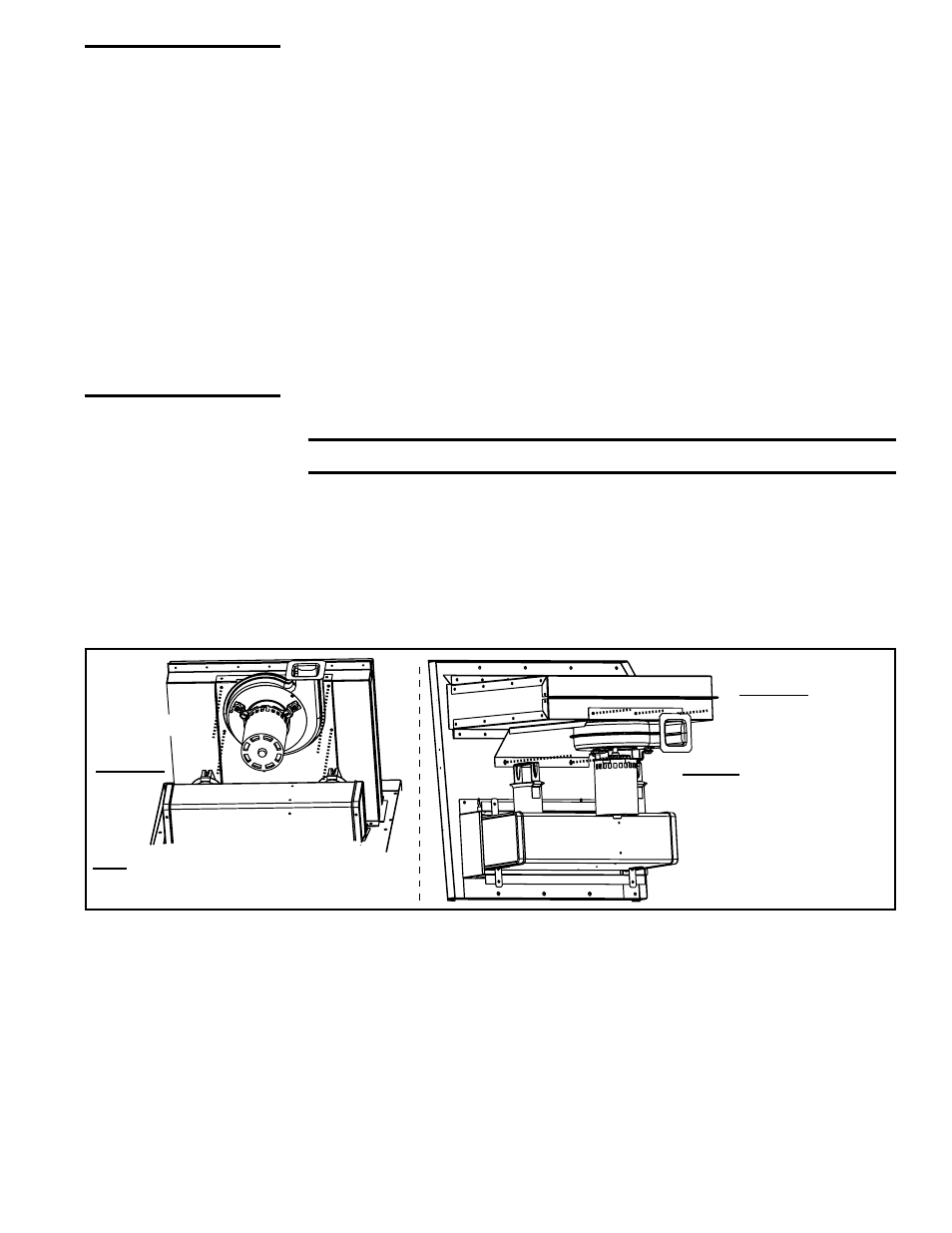
(Refer to FIGURES
12A and 12B)
������������������������������������������
���������������������������������������
�����������������������������������������������
���������������������������
�������������������������
���������������������������
������������������������������
�����������������������
�����������������
�������������������������
���������������������
�����������������������������
���������������
������
������
���������������
������������
����
�������
FIGURE 12A -
Remove the Venter
Assembly
5. Disconnect the Gas Train - At the gas valves, mark and disconnect the
wires. Disconnect the gas supply line at the connection outside the fur-
nace. Carefully remove the burner orifices and orifice adapter locking nuts.
Remove the manifold brackets. Slide the complete gas train including
valves and optional pressure switches out of the unit.
6. Remove Burner Assembly - Remove the screws above and below the
burner assembly. Carefully pull the burner assembly out of the cabinet.
With the burner assembly removed, shine a flashlight on the burner ribbons.
Look for carbon buildup, scale, dust, lint, and/or anything that might restrict flow
through the spaces between the burner ribbons. Holding the burner assembly
so that any foreign material will fall away from the burner, use a stiff bristle
brush to loosen and remove any foreign material(s). If the burner is excessively
WARNING: Turn
off the power
before performing
maintenance
procedures. Lock
disconnect switch
in OFF position.
When you turn off
the power supply,
turn off the gas
at the external
manual valve. See
Hazard Levels,
page 3.
This gas heat section is equipped with a
T
CORE
2
®
style heat exchanger.
The outside of the heat exchanger is accessible by opening the blower section
door and sliding the blower out of the unit. Remove any external dirt or dust
accumulation. Visually check the heat exchanger for cracks or holes. If a crack
or hole is observed, replace the heat exchanger.
NOTE: Inspection of the lower portion of the heat exchanger is done with the
burner removed. See the Burner Service section below for information on
inspecting the lower portion of the heat exchanger.
Burner Maintenance
This furnace is equipped with a
T
CORE2
®
style burner.
Inspect the gas heat section annually to determine if cleaning is necessary. If
there is an accumulation of dirt, dust, and/or lint, clean the compartment and
follow the instructions below to remove and clean the burner.
CAUTION: Use of eye protection is recommended.
1. Shut off the gas supply.
2. Turn off electric supply.
3. Remove the gas heat section access panel.
4. Remove the venter assembly. Disconnect the tubing. Mark and discon-
nect the three venter motor wires at the DSI control, capacitor wires at the
capacitor (if applicable), and ground screw (located on the control panel).
Follow procedure in
FIGURE 12A, STEPS 1 and 2, removing the whole
assembly including the large mounting plate.
Inspect and
Clean the Burner
NOTE: If the installation includes a Model JHUP curb duct furnace, the pro-
cedures described in Paragraph 9 also apply to the duct furnace. For illustra-
tion of a curb duct furnace, see Form I-MAPS II, Paragraph 9.4.