Venter motor and wheel – Reznor MAPSII Series REDA Users Manual User Manual
Page 23
Form RZ-NA O-MAPS II, P/N 209179 R7, Page 23
Flame Sensor - Refer to FIGURE 12B and locate the flame sensors (one on
each burner section). Disconnect the wires; remove the screws and the flame
sensor. Clean with an emery cloth.
Flame Sensors
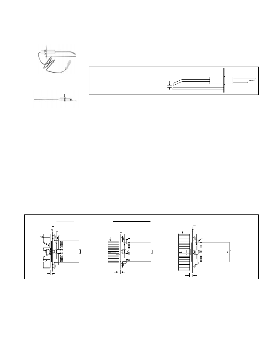
FIGURE 14 -
Ignitor showing
required Spark Gap
Measurement
��������
�������
Ignitor - Locate the ignitor. Disconnect the wire; remove the screw and the
ignitor. Clean the ignitor assembly with an emery cloth.
Spark gap must be maintained to 1/8". See
FIGURE 14.
IMPORTANT: When re-assembling, the brown ground wire must remain
attached to the ignitor.
Ignitor
Remove dirt and grease from the motor casing, the venter housing, and the
venter wheel. Venter motor bearings are permanently lubricated. Follow these
instructions for replacement of the venter motor and wheel assembly. Keep all
hardware removed to be used in re-assembling and installing the replacement
parts.
1. Turn off the gas and disconnect the electric power.
2. Open the gas heat section access panel and the electrical access panel
below the disconnect switch.
3. Disconnect the three venter motor wires at the DSI control, capacitor wires
at the capacitor (if applicable), and ground screw (located on the control
panel).
4. Holding the venter motor, remove the three or four screws that attach the
venter motor mounting plate to the venter housing. Remove the motor and
wheel assembly from the gas heater.
5. Re-assemble with the replacement venter motor and wheel assembly. See
FIGURE 15, for proper spacing.
Venter Motor
and Wheel
Replacement
Instructions
For further information and check out procedure on the direct spark ignition
system, refer to Installation Manual (Form I-MAPS II), Paragraph 19 and the
Gas Heat Section Troubleshooting Chart in Paragraph 11.
FIGURE 15 - Venter
Wheel Position on
Shaft
���������������������
�������������������
�����������������
���������������
������������������
������
�����
������������������
������������������
���
�����
��������
�����
�����
������
�����
������
�����
������������������
������������������
���
���
������������������
������������������
6. Follow the wiring diagram to re-connect the venter wires.
7. Close the access panel. Restore power to the gas heater and turn on the
gas. Check for proper operation.
Re-Assemble the
Heat Section Gas
Train, Burner, and
Venter
Instructions to Re-Assemble the Gas Heat Section (Refer to
FIGURES 12A and 12B, pages 21 and 22.)
1. Attach the Burner Assembly - Slide the entire burner assembly into posi-
tion. Insert all of the screws along the top and the bottom.
2. Attach the Gas Train - Position the gas train so that the orifice adapters
are through the brackets. Attach the manifold to the manifold brackets.