Reznor MAPSII Series REDA Users Manual User Manual
Page 27
Form RZ-NA O-MAPS II, P/N 209179 R7, Page 27
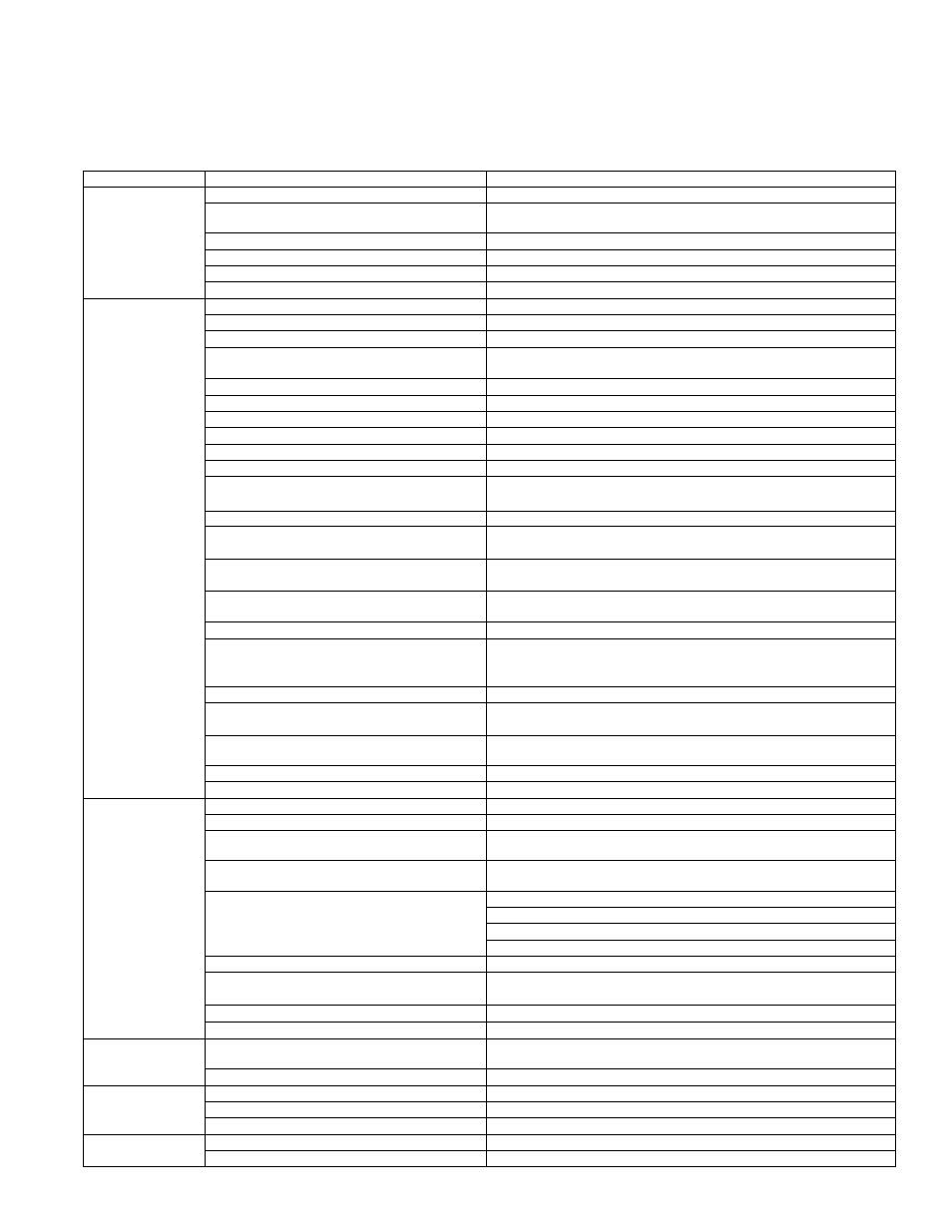
Troubleshooting - Gas Heat Section and Optional Curb Duct Furnace
PROBLEM
PROBABLE CAUSE
REMEDY
Venter motor will
not start
1. No power to unit.
1. Turn on power; check supply fuses or main circuit breaker.
2. No 24 volt power to ignition system circuit
board.
2. Turn up thermostat; check control transformer output.
3. Integrated circuit board fuse blown.
3. Correct cause. Replace fuse (type ATC or ATO, 32VDC, 3A).
4. No power to venter motor.
4. Tighten connections at circuit board and/or motor terminals.
5. Integrated circuit board defective.
5. Replace integrated circuit board.
6. Defective venter motor.
6. Replace venter motor. See Paragraph 9.
Burner will
not light
1. Manual valve not open.
1. Open manual valve.
2. Air in the gas line.
2. Bleed gas line (initial startup only).
3. Gas pressure too high or too low.
3. See installation manual, Form I-MAPS II, Paragraph 9.3.
4. No Spark:
4.
a) Loose wire connections.
a) Be certain all wire connections are solid.
b) Transformer failure.
b) Be sure 24 volts is available.
c) Incorrect spark gap.
c) Maintain spark gap at 1/8".
d) Spark cable shorted to ground.
d) Replace worn or grounded spark cable.
e) Spark electrode shorted to ground.
e) Replace if ceramic spark electrode is cracked or grounded.
f) Burner not grounded.
f) Make certain circuit board is grounded to ignitor.
g) Ignition system circuit board not grounded.
g) Make certain circuit board is grounded to furnace chassis.
h) Unit not properly grounded.
h) Make certain unit is properly field grounded to earth ground and
properly phased (L1 to hot lead L2 to neutral).
i) Ignition system circuit board fuse blown.
i) Correct cause. Replace fuse (type ATC or ATO, 32VDC, 3A).
j) Faulty circuit board.
j) If 24 volt is available to the circuit board and all other causes have
been eliminated, replace board.
5. Lockout device interrupting control circuit by
above causes.
5. Reset lockout by interrupting control.
6. Combustion air proving switch not closing
6a) Remove obstructions from vent.
6b) Replace faulty tubing to pressure switch..
7. Faulty combustion air proving switch.
7. Replace combustion air proving switch.
8. Valve not operating.
8.
a) Defective valve.
a) If 24 volt is measured at the valve connections and valve remains
closed, replace valve.
b) Loose wire connections
b) Check and tighten all wiring connections.
9. Circuit board does not power valves.
9.
a) Loose wire connections.
a) Check and tighten all wiring connections.
b) Flame sensor grounded.
b) Be certain flame sensor lead is not grounded or insulation or
ceramic is not cracked. Replace as required.
c) Incorrect gas pressure.
c) See installation manual, Form I-MAPS II, Paragraph 9.3.
d) Cracked ceramic at sensor.
d) Replace sensor.
Burner cycles on
and off
1. Gas pressure too high or too low.
1. See installation manual, Form I-MAPS II, Paragraph 9.3.
2. Burner not grounded
2. Make certain integrated circuit board is grounded to ignitor.
3. Circuit board not grounded.
3. Make certain integrated circuit board is grounded to furnace
chassis.
4. Faulty integrated circuit board
4. If 24 volt is available to the circuit board and all other causes have
been eliminated, replace board.
5. Combustion air proving switch not closing.
5.
a) Make sure unit is properly vented.
b) Remove obstructions from vent.
c) Replace faulty tubing to pressure switch.
6. Faulty combustion air proving switch.
6. Replace combustion air proving switch.
7. Flame sensor grounded.
7. Be certain flame sensor lead is not grounded or insulation or
ceramic is not cracked. Replace as required.
8. Cracked ceramic at sensor.
8. Replace sensor.
9. Incorrect polarity.
9. Reverse line volt leads to integrated circuit board.
No heat (Heater
Operating)
1. Incorrect valve outlet pressure or orifice.
1. Check valve outlet pressure. See Rating plate for manifold
pressure.
2. Cycling on limit control.
2. Check air throughput.
Venter motor will
not run
1. Circuit open.
1. Check wiring and connections.
2. Defective integrated circuit board.
2. Replace board.
3. Defective motor.
3. Replace motor.
Venter motor cuts
out on overload
1. Low or high voltage supply.
1. Correct electric supply.
2. Defective motor.
2. Replace motor.
timeter to troubleshoot the 24 volt circuit, place the meter’s test leads into the 5
or 9 pin connectors located on the ignition control. Do not remove connectors or
terminals from the electrical components. Doing so can result in misinterpreted
readings due to the ignition control board’s fault mode monitoring circuits.