0 troubleshooting (cont'd) – Reznor MAPSII Series REDA Users Manual User Manual
Page 26
Form O-MAPS II, P/N 209179 R7, Page 26
11.0 Troubleshooting (cont'd)
General Refrigeration Circuit (cont'd)
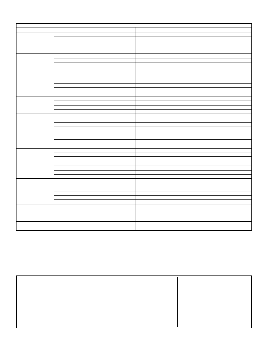
SYMPTOM
POSSIBLE CAUSE
REMEDY
G. High suction
pressure
1. Excessive load on evaporator coil.
1. Check for high entering wet bulb temperature. Check for excessive air.
2. Compressor is unloaded.
2. Check head pressure, check thermal expansion valve if not functioning
properly, check pressure drop across filter drier.
3. Expansion valve not secured to suction line or
valve defective.
3. Check the thermal expansion valve, ensure bulb is insulated.
H. High discharge
pressure.
1. Thermal expansion valve setting.
1. Check thermal expansion setting and calibrate superheat.
2. Air inlet to condenser dirty or obstructed.
2. Check for proper clearances and possible air recirculating.
3. Condenser fan motor defective.
3. Check condenser fan motor and capacitor.
I. Suction pressure is
too low.
1. Refrigerant undercharge.
1. Check pressures and subcooling.
2. Blower running backward.
2. Interchange any two wires from 3 phase disconnect.
3. Loose blower, pulley or belts.
3. Check drive pulley alignment, belt tension.
4. Defective or improperly adjusted expansion valve. 4. Check superheat and adjust thermal expansion valve.
5. Dirty filter.
5. Check filter and evaporator coil.
6. Too little air flow or low entering air temperature.
6. Check airflow and entering air wet bulb conditions.
7. Restriction in suction or liquid line.
7. Check refrigerant circuit for restriction.
J. Head pressure too
low.
1. Insufficient refrigerant charge.
1. Check subcooling, check for leak.
2. Defective or improperly adjusted expansion valve. 2. Check superheating and adjust thermal expansion valve.
3. Low suction pressure.
3. See “suction pressure too low” above.
4. Defective compressor.
4. See “high suction pressure” above.
K. Compressor short
cycles.
1. Thermostat location or malfunction.
1. Check thermostat, check heat anticipator setting.
2. Improper refrigerant charge.
2. Check subcooling, verify superheat.
3. Defective high or low pressure control.
3. Check high or low pressure switch.
4. Liquid floodback.
4. Possible tight bearings, see above.
5. Defective expansion valve.
5. Check thermal expansion valve and superheat.
6. Poor air distribution.
6. Check ductwork for recirculating.
7. High discharge pressure.
7. See “high discharge pressure” above.
8. Leaking discharge valves in compressor.
8. See “high suction pressure” above.
L. Running cycle is too
long or unit operates
continuously.
1. Refrigeration undercharged.
1. Check subcooling.
2. Dirty filter or evaporator coil.
2. Check filter, coil and airflow.
3. Dirty or clogged condenser coil.
3. Check coil and airflow.
4. Air or other non-condensables in system.
4. Check equalized high side pressure with equivalent outdoor temperature.
5. Defective compressor.
5. See “high suction pressure” above.
6. Restriction in suction and liquid line.
6. Check for restrictions in refrigerant circuit.
7. Control contacts stuck.
7. Check wiring.
M. Supply air
temperature is too high.
1. Refrigerant undercharge or leak in system.
1. Check subcooling and check for leaks.
2. Evaporator plugged with dirt or ice.
2. Check evaporator, airflow and filter.
3. Improperly adjusted or defective expansion valve. 3. Check superheat & adjust thermal expansion valve, check bulb.
4. Defective compressor.
4. Check compressor for proper operation.
5. High discharge pressure.
5. See “high discharge pressure” above.
6. Airflow is too high.
6. Check external static pressure.
N. Supply air
temperature is too low.
1. Airflow is too low.
1. Check evaporator coil; check filters, check for closed dampers or grills,
check drive for loose parts, belts, or misalignment; check external static
pressure.
2. Return air temperature too low.
2. Check entering air wet bulb conditions.
O. Liquid line is too hot. 1. Refrigerant undercharge.
1. Adjust the charge by subcooling.
2. High discharge pressure.
2. See I. above.
Troubleshooting
Gas Heat Section -
Model RDCA,
Model RDDA, and
an Optional Model
JHUP Duct Furnace
The ignition system circuit board monitors the operation of the heater and
includes two LED signal lights that indicate normal operation and various abnor-
mal conditions. If the heater fails to operate properly, check this signal to deter-
mine the cause and/or to eliminate certain causes. See operating sequence on
the wiring diagram.
Check the Lights on the DSI Integrated Control Module (Ignition
System Circuit Board)
Control Status - Green LED Codes
Steady ON ...... Normal Operation, No call for heat
Fast Flash ....... Normal Operation, Call for heat
1 Flash ............ System Lockout, Failed to detect or sustain flame
2 Flashes ........ Pressure Switch Did Not Close within 30 Seconds of Venter
Motor
3 Flashes ........ High Limit or Flame Rollout Switch Open
4 Flashes ........ Pressure Switch is Closed Before Venter Motor is Energized
Steady OFF .... Blown fuse, No Power, or Defective Board
Flame Status - Yellow LED
Codes
Steady ON ...... Flame is sensed
Slow Flash ...... Weak flame (cur-
rent below 1.0
microamps ± 50%)
Fast Flash ....... Undesired Flame
(valve open and
no call for heat)
Do not attempt to repair the DSI integrated control module (circuit board); the
only field replaceable component is the fuse.
IMPORTANT: When using a mul-