Reznor MAPSII Series REDA Users Manual User Manual
Page 17
Form RZ-NA O-MAPS II, P/N 209179 R7, Page 17
��������
�������
����������
���������
����������
�������
����������
�������������
���
�����
��������
���������������
�����������
������
�����������
�������������������������
�
�
�
�������
�������
NOTE: Compressor charges for RDCA and
RECA are the same as for Model RCA.
Compressor charges for RDDA and REDA
are the same as for Model RDA.
FIGURE 11 - Compressor Locations
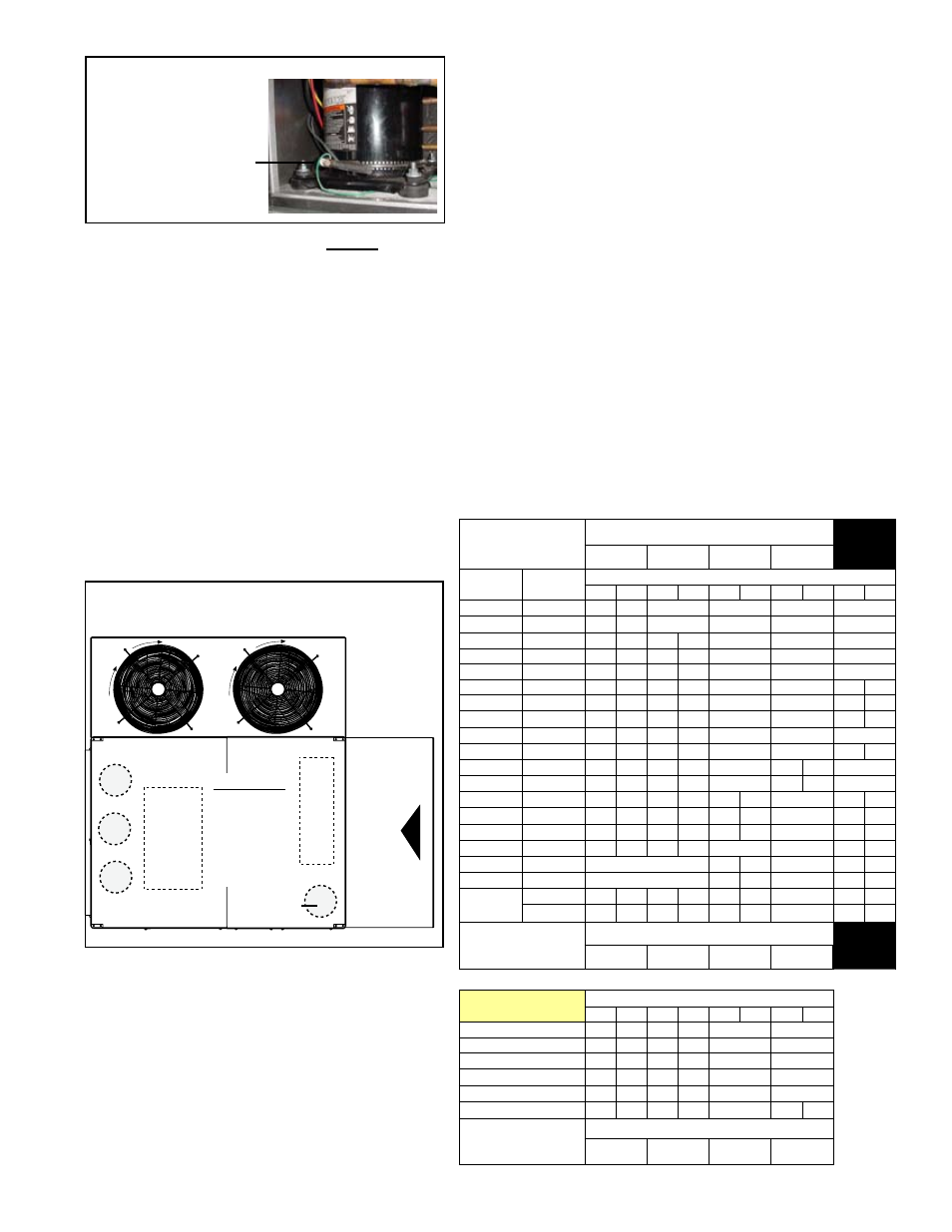
"Bellyband"
Crankcase Heater
FIGURE 10 -
Compressor
Crankcase Heater
Step 9. Charge the System
When a vacuum of at least 500 microns is reached, close gauge valve,
remove vacuum pump, and break the vacuum using system refrigerant
VAPOR
. LIQUID can be used to break the vacuum if it is connected to
the liquid line ONLY.
Charge the system according to the weights given in the table below. Be
sure to compensate the charge for the addition of the suction line filter
drier. The preferred subcooling should be
18-22°F (10.1-12.3°C) at the liq-
uid line, but may vary based on ambient conditions (See
Step 11).
NOTE : Weighing in the system charge to the specifications will help point
out system faults that may still exist.
IMPORTANT: R407C refrigerant
MUST always be charged as a liquid.
Refrigerant Charge by Model Size
and Compressor for each Circuit
Compressor
Location
(See FIGURE 11)
RCA
RDA
A
B
C
D
Dh*
*
Model
RCA
Model
RDA
Capacity (tons) and Charge (lbs)
Tons Lbs Tons Lbs Tons Lbs Tons Lbs Tons Lbs
25
--
2
5.4
N/A
N/A
N/A
N/A
37
--
3
6.1
N/A
N/A
N/A
N/A
59
--
3
6.1
2
5.1
N/A
N/A
N/A
60
--
3
5.1
2
3.5
N/A
N/A
N/A
77
--
4.5 7.6
2
5.1
N/A
N/A
N/A
78
102
4.5 7.3
2
3.7
N/A
N/A
2
3.4
90
114
4.5 7.3
3
5.1
N/A
N/A
2
3.4
108
126
6.2 8.7
3
5.1
N/A
N/A
2
3.4
109
--
6.2 8.9
3
6.2
N/A
N/A
N/A
120
144
6.2 8.7 4.5 7.3
N/A
N/A
2
3.4
139
--
4.5 8.3 4.5 7.3
N/A
3
6.0
N/A
164
--
6.2 8.7 4.5 7.3
N/A
3
5.1
N/A
166
188
4.5 8.2 6.2 9.2
3
5.8
N/A
2
3.4
184
220
4.5 6.8 6.2 8.5 4.5 6.8
N/A
3
4.5
198
234
4.5 7.5 6.2 9.5 6.2 9.5
N/A
3
4.5
176
230
4.5 7.6
10 14.5
N/A
N/A
3
9.2
226
280
12 tons / 19 lbs
6.2 9.5
N/A
3
9.2
292
346
12 tons / 27.8 lbs
12
9.5
N/A
3
9.2
374
446
10 15.6 10 15.6 10 15.6
N/A
3
10.1
428
10 15.6 10 15.6 10 15.6
N/A
3
10.1
Compressor
Location
(See FIGURE 11)
RCA
RDA
A
B
C
D
Dh*
*
* Reheat pump compressor
Model RCA with
Option AU25
Capacity (tons) and Charge (lbs)
Tons Lbs Tons Lbs Tons Lbs Tons Lbs
60
3
7.1
2
5.5
N/A
N/A
78
4.5 9.3
2
5.7
N/A
N/A
90
4.5 9.3
3
7.1
N/A
N/A
108
6.2 10.7
3
7.1
N/A
N/A
120
6.2 10.7 4.5 9.3
N/A
N/A
164
4.5 9.3 6.2 10.7
N/A
3
5.1
Compressor
Location
(See FIGURE 11)
RCA with Option AU25
A
B
C
D
Crankcase Heater (FIGURE 10) - The primary cooling
compressor on Sizes 059, 077, 109, and 139 is equipped
with a crankcase heater that must be energized for at least
24 hours before starting the unit or after a power outage of
more than 8 hours.
The belly band type crankcase heater is an external heater
attached to the lower portion of the compressor. These
external band heaters require a ground wire to the unit.