Gas valves, Combustion air pressure switch, Limit control – Reznor MAPSII Series REDA Users Manual User Manual
Page 24
Form O-MAPS II, P/N 209179 R7, Page 24
9.0 Gas Heat
Section
Maintenance
(cont'd)
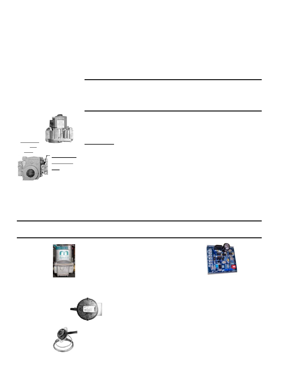
Gas Valves
Carefully remove external dirt accumulation from the valve and check wiring
connections.
The combination gas valves must be checked annually to ensure that each
valve is shutting off gas flow completely.
Instructions:
1) Locate the 1/8" NPT pressure tap on the first combination valve (see illus-
tration on the left).
2) Turn the manual valve OFF to prevent flow to the manifold. Connect a
manometer to the 1/8” outlet pressure tap of the first single-stage valve.
NOTE: A manometer (fluid-filled gauge) with an inches water column scale
is recommended.
Turn the manual valve ON and the heater off.
3) Use your finger to fully block the burner orifice. Continue blocking the ori-
fice for several seconds and observe the manometer. If any pressure is
indicated, the gas valve is leaking. A leaking gas valve must be replaced
before the heater is put back in operation.
4) Repeat the test with each single-stage gas valve.
Single-
Stage
Gas
Valve
(Side View
and Top
View)
WARNING: The operating valve is the prime safety shutoff.
All gas supply lines must be free of dirt or scale before con-
necting to the unit to ensure positive closure. See Hazard
Levels, page 3.
1/8” Outlet
Pressure
Tap
Units with optional 6:1 turndown (Option AG57) include
a modulating/regulating valve in addition to the two
single-stage valves. The modulating/regulating valve
is controlled by a signal conditioner responding to the
system controller to provide the modulated gas flow
for 6:1 turndown. The only field maintenance to the
modulating gas valve is to carefully remove dirt accu-
mulation and to check wiring connections.
Modulating/
Regulating
Valve in
Optional 6:1
Gas Control
Maxitrol Signal
Conditioner used in
Control Option AG57
P/N
131470
Combustion Air
Pressure Switch
See
FIGURE 1A, page 5, Item 17, for location. If it is determined
that the pressure switch needs replacing, use only the factory-autho-
rized replacement part that is designed for the model and size of gas
heater being serviced.
Limit
Control
The limit control is located in the blower compartment with the capillary extend-
ing across the heat exchanger. (
NOTE: For Model JHUP curb duct furnace,
see Form I-MAPS, Paragraph 9.4 for location.)
If it is determined that the limit control needs replacing, use only a factory-
authorized replacement part that is designed for the size of heater.
Install the orifice adapter nuts and the gas orifices being careful not to
damage the venturi tubes and/or the brackets. Re-connect the wires to the
gas valves.
3. Re-attach the venter assembly. (If replacing venter parts, follow instructions
above.) Re-connect the tubing and wires.
4. Close the access panel.
5. Reconnect the gas supply at the union outside of the cabinet. Leak test the
connection with leak detecting solution.
6. Turn on the electric and the gas. Check for proper operation.
Re-Assemble the Heat Section Gas Train, Burner, & Venter (cont'd)
CAUTION: DO NOT bottom out the gas valve regulator adjusting screw. This can result in
unregulated manifold pressure causing excess overfire and heat exchanger failure.