2 venting – Reznor HRPD (Outdoor Duct Furnaces) Unit Installation Manual User Manual
Page 9
Form I-RP/HRPD, P/N 132210 R14, Page 9
For Propane: When the heater leaves the factory, the combination valve is set so that
the outlet gas pressure of a single-stage valve or high fire of a two-stage valve is 10"
w.c. Low fire on a two-stage valve is set to 5" w.c. Inlet pressure to the valve must be
a minimum of 11" w.c. and a maximum of 14" w.c.
Before attempting to measure or adjust manifold gas pressure, the inlet (supply) pres-
sure must be within the specified range for the gas being used both when the heater is
in operation and on standby. Incorrect inlet pressure could cause excessive manifold
gas pressure immediately or at some future time.
Instructions to Check Valve Outlet (Manifold) Pressure:
CAUTION: DO NOT bottom out the gas valve regulator adjusting screw. This can
result in unregulated manifold pressure causing overfire and heat exchanger
failure.
1) With the manual valve (on the combination valve) positioned to prevent flow to the
main burners, connect a manometer to the 1/8" pipe outlet pressure tap in the valve.
NOTE: A manometer (fluid-filled gauge) is recommended rather than a spring type
gauge due to the difficulty of maintaining calibration of a spring type gauge.
2) Open the valve and operate the heater. Measure the gas pressure to the manifold.
To measure the low stage pressure on units equipped with a two-stage valve, discon-
nect the wire from the "HI" terminal on the valve. (Be sure to reconnect the wire.)
Normally adjustments should not be necessary to the factory preset regulator. If adjust-
ment is necessary, set pressure to correct settings by turning the regulator screw IN
(clockwise) to increase pressure. Turn regulator screw OUT (counterclockwise) to
decrease pressure. Consult the valve manufacturer's literature provided with the fur-
nace for more detailed information.
6.2 Venting
Locate power-vented furnaces so that flue discharge is not directed at fresh air inlets.
The flue discharge openings are located on the side of the furnace just above the con-
trol access panel. The position of this opening discourages recirculation of combustion
products and provides for furnace operation in all normal weather conditions.
Optional Vertical Flue
Discharge (Option
CC3)
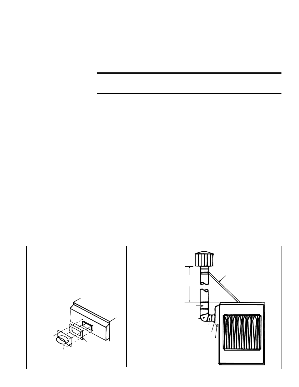
These power vented furnaces are certified with four feet of vertical pipe attached as
shown in
FIGURES 5A and 5B. The distance is measured from the top of the unit to
the bottom of the vent cap. The option package includes the 5" vent cap, the adapter
assembly and the seal plate. The vent pipe and supports are field supplied.
Optional vertical vent piping provides compliance with local codes that require either
10-ft horizontal or 4-ft vertical clearance between the flue outlet and fresh air intake of
the heating system and/or the building.
Oval Adapter Assy,
PN/ 103025
Venter Seal Plate,
P/N 43446
FIGURE 5A - Installation of Adapter
for Optional Vertical Flue Discharge
(Option CC3, P/N 45021)
Attach the venter seal plate and oval
adapter assembly with sheetmetal
screws. Use venter seal plate as drill
template.
5 Vent Cap,
P/N 110052
5 dia Flue Pipe
4
(1.2M)
5 dia
90° Elbow
18 (457mm) Straight Pipe
Oval Adapter Assy
Combustion Air Intake
Support angles for flue pipe.
Recommended size is
1/2x1/2, 20 gauge
FIGURE 5B -
Installation of
the Vent Cap
(included in the
option pkg) and
the field-supplied
piping and
supports