0 uncrating and preparation, 0 furnace location (cont'd), 1 uncrating and inspecting – Reznor HRPD (Outdoor Duct Furnaces) Unit Installation Manual User Manual
Page 4
Form I-RP/HRPD, P/N 132210 R14, Page 4
3.0 Uncrating and
Preparation
3.1 Uncrating and Inspecting
This furnace was test operated and inspected at the factory prior to crating and was in
operating condition. If the furnace has incurred any damage in shipment, document the
damage with the transporting agency and immediately contact an authorized Reznor
®
distributor. If you are an authorized Distributor, follow the FOB freight policy procedures
as published by Reznor, LLC.
Check the rating plate for the gas specifications and electrical characteristics of the
furnace to be sure that they are compatible with the gas and electric supplies at the
installation site.
3.2.1 Shipped-Separate Components
Read this booklet and become familiar with the installation requirements of your par-
ticular furnace. If you do not have knowledge of local requirements, check with the local
gas company or any other local agencies who might have requirements concerning
this installation. Before beginning, make preparations for necessary supplies, tools,
and manpower.
Check to see if there are any field-installed options that need to be assembled to the
furnace prior to installation.
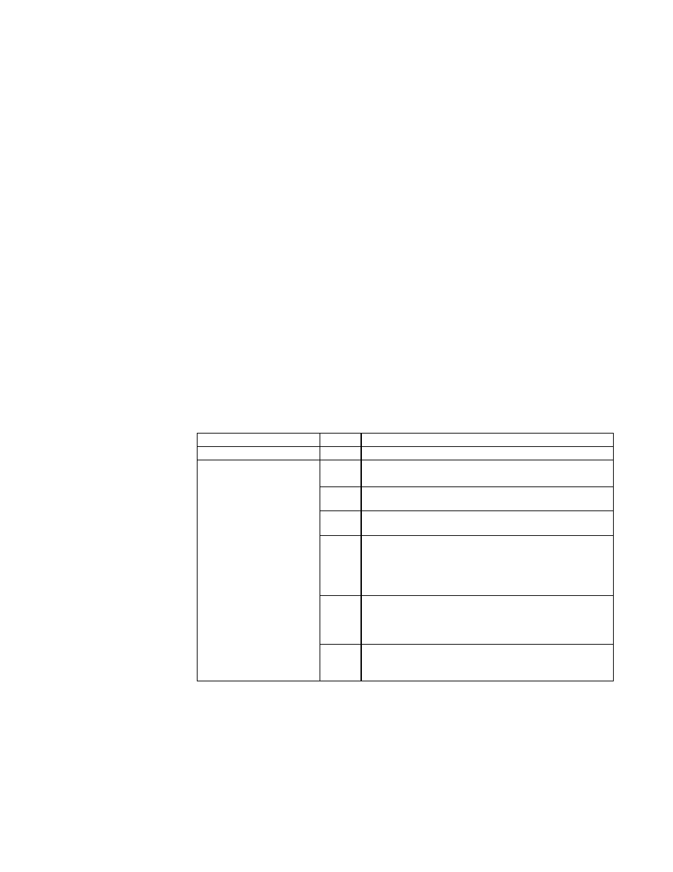
Option Parts - Some gas control options will have parts either shipped loose with the
heater or shipped separately. If your unit is equipped with any of the gas control options
in the table below, be sure these parts are available at the job site.
2.0 Furnace
Location
(cont'd)
2.2 Combustion Air Requirements (cont'd)
3.2 Preparing the
Furnace for
Installation
Other shipped-separate options could include a gas shutoff valve, a vertical vent termi-
nal, a thermostat, an optional control, and/or a disconnect switch.
Check to see if there are any field-installed options that need to be assembled to the
furnace prior to installation.
3.2.2 Instructions for
Reversing Airflow by
Changing Direction
of Heat Exchanger Air
Baffles - Model RP
Model RP duct furnaces are equipped with directional air baffles between the heat
exchanger tubes as shown in
FIGURE 1. Facing the control compartment of the fur-
nace, the standard direction of airflow is from left to right.
If the installation requires direction of airflow from right to left when facing the con-
trol compartment, follow the instructions in
FIGURE 1 to reposition the directional air
baffles at the installation site.
any condensation that is present in the heat exchanger or associated parts. The result
is hydrochloric acid which readily attacks all metals including 300 grade stainless steel.
Care should be taken to separate these vapors from the combustion process. This may
be done by wise location of the furnace with regard to exhausters or prevailing wind
direction. Remember, chlorine is heavier than air. This fact should be kept in mind when
determining installation locations of heating equipment and building exhaust systems.
Application
Option Shipped Separate Components
Heating -- Gas Control AG7
Thermostat,
P/N 48033
Makeup Air -- Gas
Control Options
(NOTE: If an optional
remote console
is ordered, the
control switch and
temperature selector
may be mounted on the
console.)
AG3,
AG4
Control Switch,
P/N 29054
AG8
Control Switch,
P/N 29054; Sensor & Mixing Tube,
P/N 48041
AG9
Control Switch,
P/N 29054; Remote Temperature
Selector,
P/N 48042; Sensor & Mixing Tube, P/N 48041
AG15
Control Switch,
P/N 29054; Remote Temperature
Selector,
P/N 115848; Stage Adder Module, P/N 115849
-
(1) for RP or (3) for HRPD; Discharge Air Sensor
Holder,
P/N 115850; Discharge Air Sensor Holder
Bracket,
P/N 213612
AG17
Control Switch,
P/N 29054; Remote Temperature
Selector,
P/N 115848; Stage Adder Module, P/N 115849;
Discharge Air Sensor Holder,
P/N 115850; Discharge Air
Sensor Holder Bracket,
P/N 213612
AG39,
AG41
Remote Temperature Selector,
P/N 174849;
Temperature Sensor,
P/N 133228; Mixing Tube,
P/N 90323