0 dimensions and clearances, 1 dimensions – Reznor HRPD (Outdoor Duct Furnaces) Unit Installation Manual User Manual
Page 5
Form I-RP/HRPD, P/N 132210 R14, Page 5
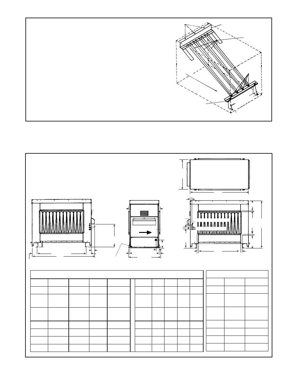
FIGURE 1 - Model RP Heat Exchanger with
Directional Air Baffles
Top Baffle
Support
Screws
B
Bottom
Baffle Support
Bracket
s
Air Discharge
Direction of
Airflow
Screw C
Right
Lef
t
Screws A
Screw C
Airflow
Baffles
4.0 Dimensions and Clearances
4-1/16 (103)
3-9/32 (83)
D Mounting
A
4-1/16 (103)
Alternate
Thermostat
Connection
Alternate
Electric
Connections
1/4 (6mm)
diameter condensate
drain (2 per side)
1/2
(13)
25 (635) Mtng
26 (660)
2-1/2 (64)
1/2
(13)
6-1/32 (153)
Gas
Connection
(see table
for size)
Airflow
Left Side View
2-1/2 (64)
18-3/32
(460)
15/16
(24)
15/16
(24)
24-1/4
(616)
B
Top
View
1-1/8 (29)
16-1/4
(413)
3/4 (19)
8-15/32
(215)
3/4
(19)
18
(457)
38-17/32
(979)
10-9/16
(268)
C
Front View
Thermostat Connection
Electric Connections
1-1/8 (29)
3/4 (19)
3/4
(19)
1-21/32 (42)
Rear View
FIGURE 2A - Dimensions,
Model Series RP
Model Series RP Dimensions - inches ± 1/8 / mm ±3
RP
A
B
C
D
RP
A
B
C
D
125 30-15/16 28-1/2 15-1/4 20-5/16
125
786 648 387 516
150,
175
36-7/16
34
20-3/4 25-13/16
150,
175
914 864 527 656
200,
225 41-15/16 39-1/2 26-1/4 31-5/16
200,
225 1065 1003 667 795
250
50-3/16 47-3/4 34-1/2 39-9/16
250 1275 1213 876 1005
300
50-3/16 47-3/4 34-1/2 39-9/16
300 1275 1213 876 1005
350 55-11/16 53-1/4
40
45-1/16
350 1414 1353 1016 1145
400
61-3/16 58-3/4 45-1/2 50-9/16
400 1554 1492 1156 1284
Gas Connection (inches)
RP
Natural Propane
125
1/2"
1/2"
150,
175
1/2"
1/2"
200,
225
1/2"
1/2"
250
1/2"
1/2"
300
3/4"
1/2"
350
3/4"
1/2"
400
3/4"
1/2"
4.1 Dimensions
Instructions for repositioning baffles to reverse
airflow direction
1) Remove Screws "A".
2) Lift each baffle slightly and slide forward removing each
individual baffle completely from the heat exchanger.
3) Remove the top baffle support. Re-use screws "B" and
install the top baffle support on the opposite end of the
heat exchanger.
4) Re-install the bottom baffle support and brackets on the
opposite end of the heat exchanger.
5) Reverse Steps 1 and 2 -- re-installing all of the baffles.