Reznor HRPD (Outdoor Duct Furnaces) Unit Installation Manual User Manual
Page 19
Form I-RP/HRPD, P/N 132210 R14, Page 19
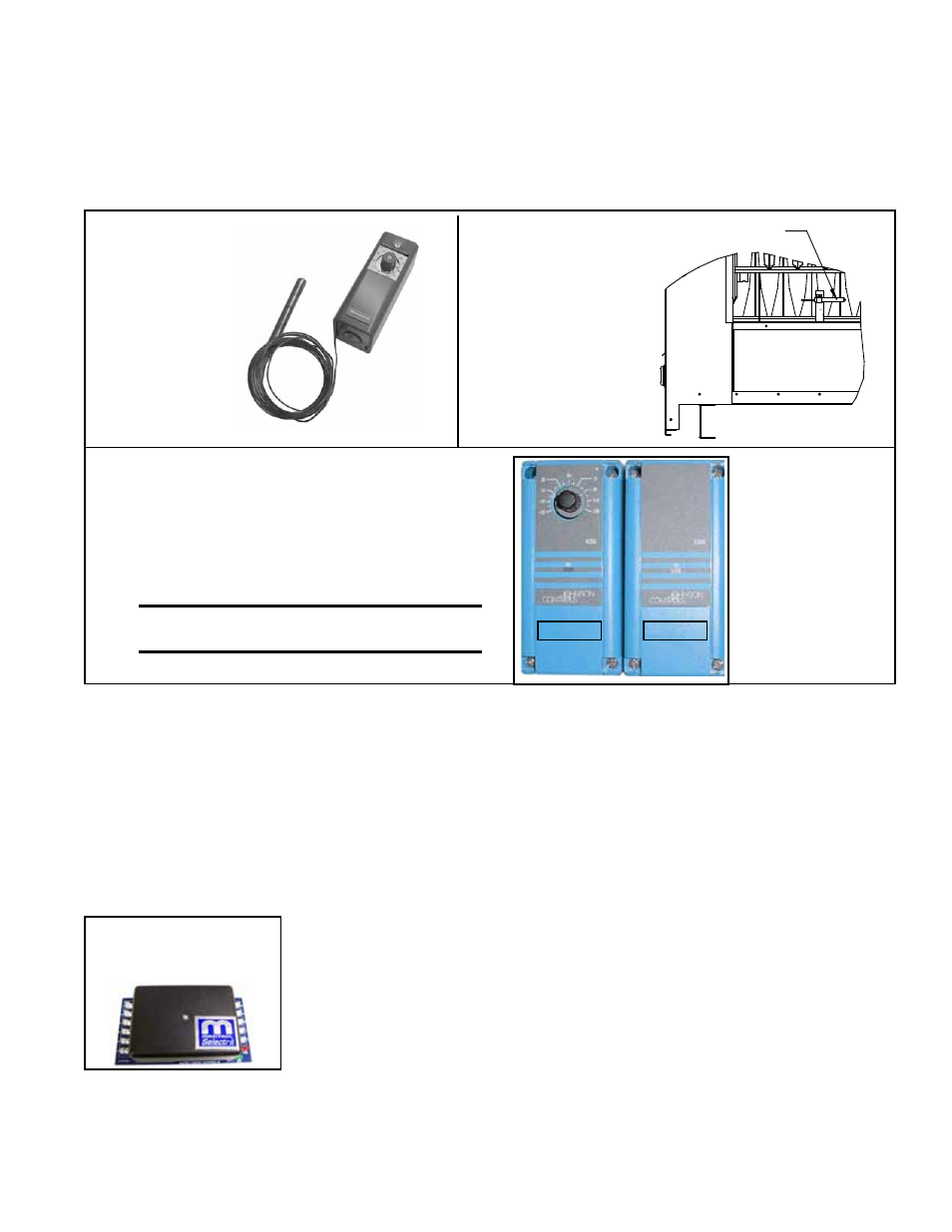
FIGURE 12B -
Ductstat Bulb
(factory installed)
FIGURE 12A - Ductstat Control
in Option AG3 and AG4
Factory
set at
70°F
Adjustable range
0-100°F with a fixed
differential of 3°F.
Ductstat Sensor Bulb
- Option AG3 or AG4
FIGURE 13 - Remote Temperature Selector (A)
and Stage-Adder Module (B) In Gas Control
Options AG15 and AG17
(A)
CAUTION: Be sure heat/cool selector
switch is set at "Heat" position.
(B)
8.4.4 Optional
Electronic Modulation
The type and capability of the electronic modulation system, depends on the option
selected. Electronic modulation options are identified by a suffix to the Serial No.
printed on the heater rating plate. AG7 is identified as MV1; AG8 is identified as MV3;
AG9 is identified as MV4; AG21 is identified as MVA; AG39 is identified as MP1; and
AG40 is identified as MP2. AG39 and AG40 are available only on Model RP. AG41 is
identified as MP3 and AG42 is identified as MP4. Both AG41 and AG42 apply to Model
HRPD.
Installation NOTE: Model RP 350 and 400 and Model HRPD 350, 400, 500, 600, 700,
and 800 with electronic modulation require a minimum of 6" w.c. natural gas supply
pressure.
to 130°F. The sensing probe and remote modules (
FIGURE 13) are shipped separately
for field installation. Follow the instructions Paragraph 6.3.5 for installing the sensor.
Refer to the wiring diagram with the unit and the manufacturer's instructions for wiring
and installing the remote modules.
CAUTION: Make sure heat/cool selector switch
is set on "HEAT". Depending on the staging provided, there will be one module for
selecting temperature and either one or two stage-adder modules.
See
TABLE A or B, page 18, for recommended settings and staging sequence of two-
stage options.
NOTE: Model HRPD with Option AG15
uses three stage adder modules.
FIGURE 14A -
Amplifier in Options
AG7, AG8, and AG9
Electronic Modulation between 50% and 100% Firing Rate (Options AG7,
AG8, AG9)
Depending on the heat requirements as established by the thermistor sensor, the
burner modulates between 100% and 50% firing. The thermistor is a resistor that is
temperature sensitive in that as the surrounding temperature changes, the Ohms resis-
tance changes through the thermistor. This change is monitored by the solid state
control center (amplifier) which furnishes varying DC current to the modulating valve to
adjust the gas input.
Each modulating valve is basically a regulator with electrical means of raising and
lowering the discharge pressure. When no DC current is fed to this device, it functions
as a gas pressure regulator, supplying 3.5" w.c. pressure to the main operating valve.
Refer to the wiring diagram supplied with the furnace for proper wiring connections. Elec-
tronic modulation for heating controlled by a specially designed room thermostat (60°-
85°F) is identified as Option AG7. Electronic modulation control systems for makeup