0 mechanical (cont'd) – Reznor HRPD (Outdoor Duct Furnaces) Unit Installation Manual User Manual
Page 12
Form I-RP/HRPD, P/N 132210 R14, Page 12
6.3 Duct Furnace Air
Flow (cont'd)
6.3.4 Duct
Connections (cont'd)
6.0 Mechanical
(cont'd)
Heater
Duct
Access
Panel in Duct
6
(152mm)
10 (254mm)
1
2
3
4
U Channel
(See FIGURE 11.)
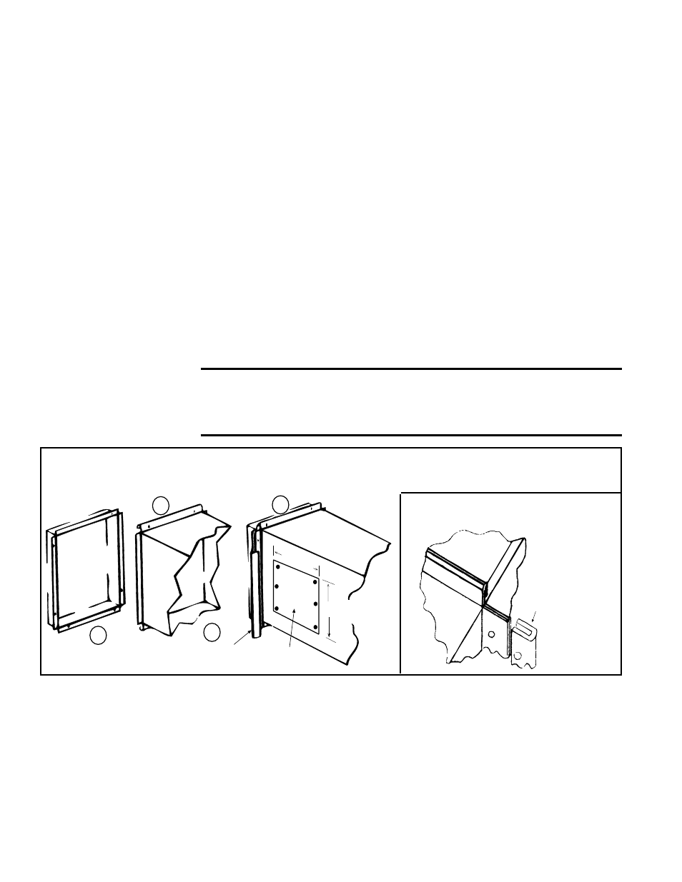
FIGURE 9A -
Connecting Supply Air
Duct to the Furnace
Furnace
Duct
U Channel
of Light Gauge
Metal
(1) Flanges on the furnace (heat exchanger) turn out as shown. (2) Shape duct connection as shown -- "U" on top
and bottom; "L" on sides. (3) Slide "U" channels over furnace top and bottom flanges making connection. (4) Form
"U" channels to seal sides.
Drill and lock with sheetmetal screws.
FIGURE 9B - "U" Channel Duct
Connection
•
Through Unheated Space - Insulate all exposed warm air ducts passing through
an unheated space with at least 1/2" (1" is recommended) of insulation.
•
Duct Supports - Suspend all ducts securely from building members. Do not sup-
port ducts from unit duct connections.
•
Duct Sizing - Proper sizing of the supply air ductwork is necessary to ensure a
satisfactory heating installation. The recognized authority for such information is
the Air Conditioning Contractors Association, 2800 Shirlington Road, Suite 300,
Arlington, VA 22206 (www.acca.org). A manual covering duct sizing in detail may
be purchased directly from them.
•
Removable Panels - The ducts should have removable access panels on both
upstream and downstream sides of the furnace. These openings must be acces-
sible when the furnace is in service and should be a minimum of 6" x 10" in size
so smoke or reflected light may be observed inside the casing to indicate the pres-
ence of leaks in the heat exchanger. The covers for the openings must be attached
in such a manner as to prevent leakage. See
FIGURE 9A.
•
Horizontal Discharge Duct Length - A minimum horizontal duct run of 24"
(610mm) is
recommended before turns or branches are made in the duct system
to reduce losses at the furnace outlet.
•
Supply Air Duct/Furnace Horizontal Connection - The seal between the fur-
nace and the duct must be mechanical. Duct connection should be made with "U"
type flanges on the top and bottom of the connecting duct. Slide the duct over the
flanges of the heater giving an airtight fit. Provide "U" type channels for the other
side flanges to ensure tight joints. Use sheetmetal screws to fasten ducts and "U"
channels to the furnace flange. See
FIGURES 9A and 9B.
CAUTION: Joints where supply air ducts attach to the furnace
must be sealed securely to prevent air leakage. Leakage can
cause poor combustion, pilot problems, shorten heat exchanger
life, and cause poor performance.
Requirements and Suggestions (cont'd)
6.3.5 Discharge Air
Sensor for Makeup
Air Application
Makeup air Options AG3 and AG4 have a unit mounted ductstat with a capillary sensor
that is factory-installed in the unit discharge (See Paragraph 8.4.3).
Makeup air Options AG15, AG17, AG8, AG9, AG39, AG40, AG41, and AG42 require
field installation of the sensor in the discharge ductwork.
Option AG15 and AG17 use the box and sensor holder in
FIGURE 10A.
Options AG8, AG9, AG39, and AG41 include a sensor and mixing tube like the one
illustrated in
FIGURE 10B. Options AG40 and AG42 require a field-supplied sensor.
Follow the instructions below to install the sensor in the ductwork.
For control information, see Paragraph 8.4.