0 mechanical (cont'd), 3 duct furnace airflow, 1 pressure drop and temperature rise by size – Reznor HRPD (Outdoor Duct Furnaces) Unit Installation Manual User Manual
Page 10: 2 duct furnace blower connections
Form I-RP/HRPD, P/N 132210 R14, Page 10
6.0 Mechanical
(cont'd)
6.3.1 Pressure Drop and Temperature Rise by Size
The duct furnace must be installed on the positive pressure side of the field supplied
blower. The air throughput must be within the CFM range stated on the heater rat-
ing plate. The air distribution must be even over the entire heat exchanger. Turning
vanes should be used in elbows or turns in the air inlet to ensure proper air distribu-
tion (See Paragraph 6.3.2). If it is determined that the blower CFM is greater than
allowed or desirable, see Paragraph 6.3.3 for instructions on determining the correct
size of bypass duct required. To determine temperature rise, the inlet and outlet air
temperatures should be measured at points not affected by heat radiating from the
heat exchanger. The charts below show the approved temperature rise range with the
required CFM and the internal pressure drop for each size of unit.
6.3 Duct Furnace
Airflow
Model RP (80% thermal efficient)
Size
125
150
175
200
225
250
300
350
400
Temp Rise CFM P.D. CFM P.D. CFM P.D. CFM P.D. CFM P.D. CFM P.D. CFM P.D. CFM P.D. CFM P.D.
50°F
1840 0.50 2210 0.38 2580 0.52 2945 0.42 3315 0.53 3685 0.40 4420 0.58 5160 0.65 5895 0.7
60°F
1535 0.33 1840 0.26 2150 0.35 2455 0.28 2765 0.36 3070 0.28 3685 0.39 4300 0.44 4915 0.5
70°F
1315 0.25 1580 0.19 1840 0.26 2105 0.22 2370 0.27 2630 0.23 3160 0.29 3685 0.31 4210 0.3
80°F
1150 0.21 1380 0.15 1610 0.19 1840 0.17 2070 0.22 2300 0.22 2765 0.25 3225 0.25 3685 0.3
90°F
1020 0.18 1225 0.12 1430 0.16 1635 0.14 1840 0.17 2045 0.21 2455 0.22 2865 0.23 3275 0.2
Model HRPD
SIZE
250
300
350
400
500
600
700
800
Temp Rise CFM PD CFM PD CFM PD CFM PD CFM PD CFM PD CFM PD CFM PD
40°F
4630 1.97 5556 1.45 6481 2.02 7407 1.70 9259 1.53 11111 2.14 12963 2.09 14815 2.09
50°F
3704 1.26 4444 0.92 5185 1.29 5926 1.09 7407 0.98 8889 1.37 10370 1.34 11852 1.34
60°F
3086 0.88 3704 0.64 4321 0.90 4938 0.76 6173 0.68 7407 0.95 8642 0.93 9877 0.93
70°F
2646 0.64 3175 0.47 3704 0.66 4233 0.56 5291 0.50 6349 0.70 7407 0.68 8466 0.68
80°F
2315 0.49 2778 0.36 3241 0.51 3704 0.43 4630 0.38 5556 0.54 6481 0.52 7407 0.52
90°F
2058 0.39 2469 0.29 2881 0.40 3292 0.34 4115 0.30 4938 0.42 5761 0.41 6584 0.41
100°F
1852 0.32 2222 0.23 2593 0.32 2963 0.27 3704 0.24 4444 0.34 5185 0.33 5926 0.33
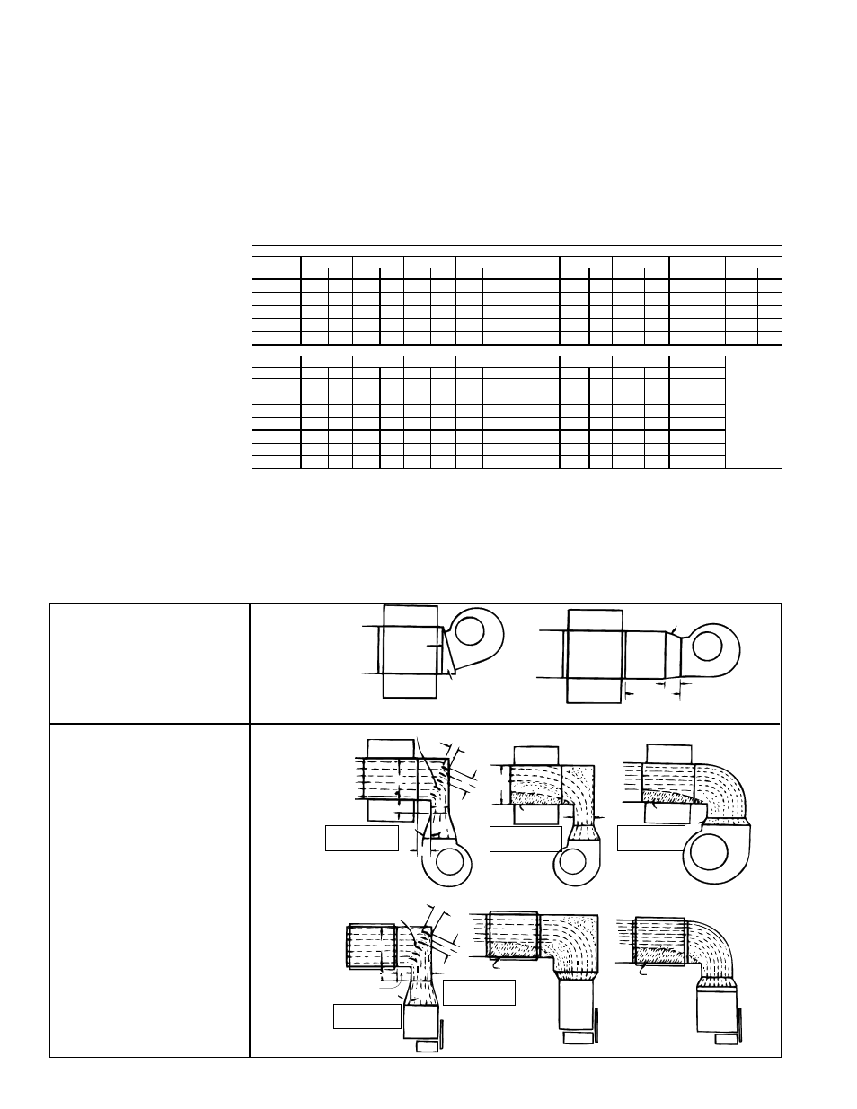
6.3.2 Duct Furnace
Blower Connections
Proper arrangement of blower and duct furnace with respect to angle of approach of
the duct connection and the arrangement of the discharge opening of the blower is
required. Blowers should be bottom horizontal discharge when coupled to the duct
furnace. When a top horizontal discharge blower is connected to the duct furnace, be
sure that sufficient length of duct is provided to permit even flow of air at the end of the
duct. Or, baffles may be inserted between the blower and the heater to assure an even
flow of air across the heat exchanger.
Direct
Coupling
Slanted Transition
Suggested blower connections for straight through airflow.
Use either method for good air coverage and efficient operation.
15°
6 (152mm)
Remote
24
(610mm)
minimum
Turning Vanes
3(76mm)
3(76mm)
3(76mm)
6 (152mm)
6
(152mm)
X
15°
Y
No air
X
No air
Z
NOTE: X should
never be less than
1/2 Y
NOTE: X should
never be less
than 1/2 Y
NOTE: Angle Z
should never be
more than 15°
Turning Vanes
3(76mm)
3(76mm)
3(76mm)
6 (152mm)
6 (152mm)
Z
NOTE: Angle Z
should never be
more than 15°
X
15°
No air
GOOD
GOOD
POOR
POOR
POOR
No air
POOR
Y
Y
NOTE: X should
never be less
than 1/2 Y
FIGURE 6A -
Straight
Through Air
FIGURE 6B -
With Elbows
Up or Down
FIGURE 6C -
With Elbows
Right or Left