0 controls (cont'd), 4 gas controls (cont'd) – Reznor HRPD (Outdoor Duct Furnaces) Unit Installation Manual User Manual
Page 20
Form I-RP/HRPD, P/N 132210 R14, Page 20
8.0 Controls
(cont'd)
8.4 Gas Controls
(cont'd)
8.4.4 Optional Electronic Modulation (cont'd)
Electronic Modulation
between 20-28% and
100% Firing Rate -
Options AG39 & AG40
(natural gas only Model
RP only; not available
on Size 350) and
Options AG41 & AG42
(natural gas only Model
HRPD; not available on
Size 700)
Depending on the size, furnaces equipped with electronic modulation Option AG39,
AG40, AG41, or AG42, have a 20-28% turndown ratio. The furnace will ignite at any
input rate in the available range and will maintain average thermal efficiencies equal to
or greater than the thermal efficiency at full fire.
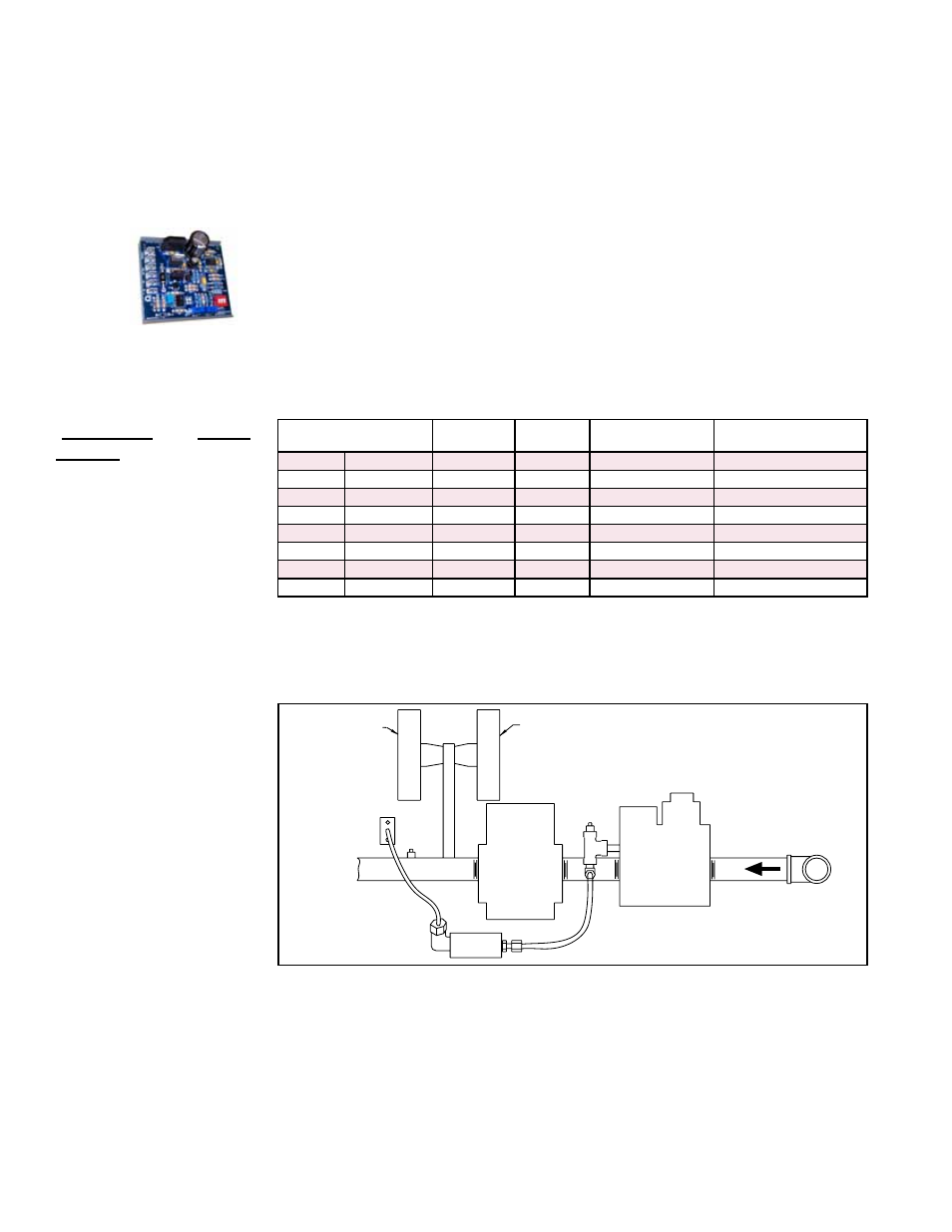
FIGURE 14B - Maxitrol
Signal Conditioner in
Options AG21, AG40, &
AG42
gu
Carryover
Regulator
Modulating
Valve
Single-
Stage Gas
Valve
P rimary Gas
Flow Pressure
Switch
White Label
1.1 w.c.
Gas Flow
Pressure Switch
White Label
1.1 w.c.
FIGURE 15 - Option
Manifold Arrangement
Model / Size
Maximum
Turndown
MBH Inlet
Range
Inlet Pressure to
Modulating Valve
Gas Supply Pressure
Required
RP 125
HRPD 250
20%
25-125
3.9" w.c.
5" w.c.
RP 150
HRPD 300
27%
40.3-150
3.7" w.c.
5" w.c.
RP 175
HRPD 350
23%
40.3-175 3.7" w.c.
5" w.c.
RP 200
HRPD 400
26%
51.8-200 3.9" w.c.
5" w.c.
RP 225
23%
51.8-225 3.9" w.c.
5" w.c.
RP 250
HRPD 500
28%
69-250
4.0" w.c.
5" w.c.
RP 300
HRPD 600
23%
69-300
4.0" w.c.
5" w.c.
RP 400
HRPD 800
25%
100-400
4.4" w.c.
6" w.c
The gas train includes a single-stage gas valve, a modulating valve, and two gas pres-
sure switches. The burner rack is equipped with one flash carryover and a regulated
gas lighter tube system. The carryover lighter tube receives its gas supply through the
regulator, simultaneously with the gas to the burner. Control of the system is through a
Maxitrol amplifier with a corresponding remote temperature dial
Description of
Operation - Options
AG39, AG40, AG41,
AG42
The gas supply (see pressure requirements in the table above) connects to the single-
stage gas valve. To compensate for additional pressure loss through the modulating
valve, the single-stage gas valve has a custom outlet pressure setting higher than
when it is used on a standard gas manifold. The pilot tubing connects to the pilot port
on the single-stage gas valve. When the valve receives a call for heat from the ampli-
fier and pilot is established, gas flow from the single-stage valve goes to both the mod-
ulating valve and the regulated lighter tube system. When the signal from the amplifier
to the modulating valve requires less-than-high fire operation, the modulating valve
functions to lessen the gas flow to the burner to reduce the input rate to that required to
maintain the desired temperature. When the input rate is reduced enough to decrease
air applications controlled by a field-installed duct sensor (See Paragraph 6.3.5.) and
temperature selector (55-90°F) are identified as either Option AG8 or Option AG9.
The temperature selector setting for Option AG8 is on the amplifier; Option AG9 has a
remote temperature selector. Both systems are available with an override thermostat.
Computer Controlled Electronic Modulation between 50% and 100%
Firing Rate (Option AG21)
With this option the furnace is equipped with a Maxitrol signal conditioner which oper-
ates much the same way as the amplifier above to control the regulator valve. The con-
ditioner accepts an input signal of either 4-20 milliamps or 0-10 volts from a customer-
supplied control device such as a computer. With the dip switches on the conditioner in
the "on" positions, the conditioner accepts a 4-20 milliamp signal. In the "off" positions,
the conditioner accepts a 0-10V signal. The conditioner converts the signal to the 0 to
20 volt DC current required to control the modulating valve.