6 burners and carryover system, 7 burner air adjustment – Reznor HRPD (Outdoor Duct Furnaces) Unit Installation Manual User Manual
Page 23
Form I-RP/HRPD, P/N 132210 R14, Page 23
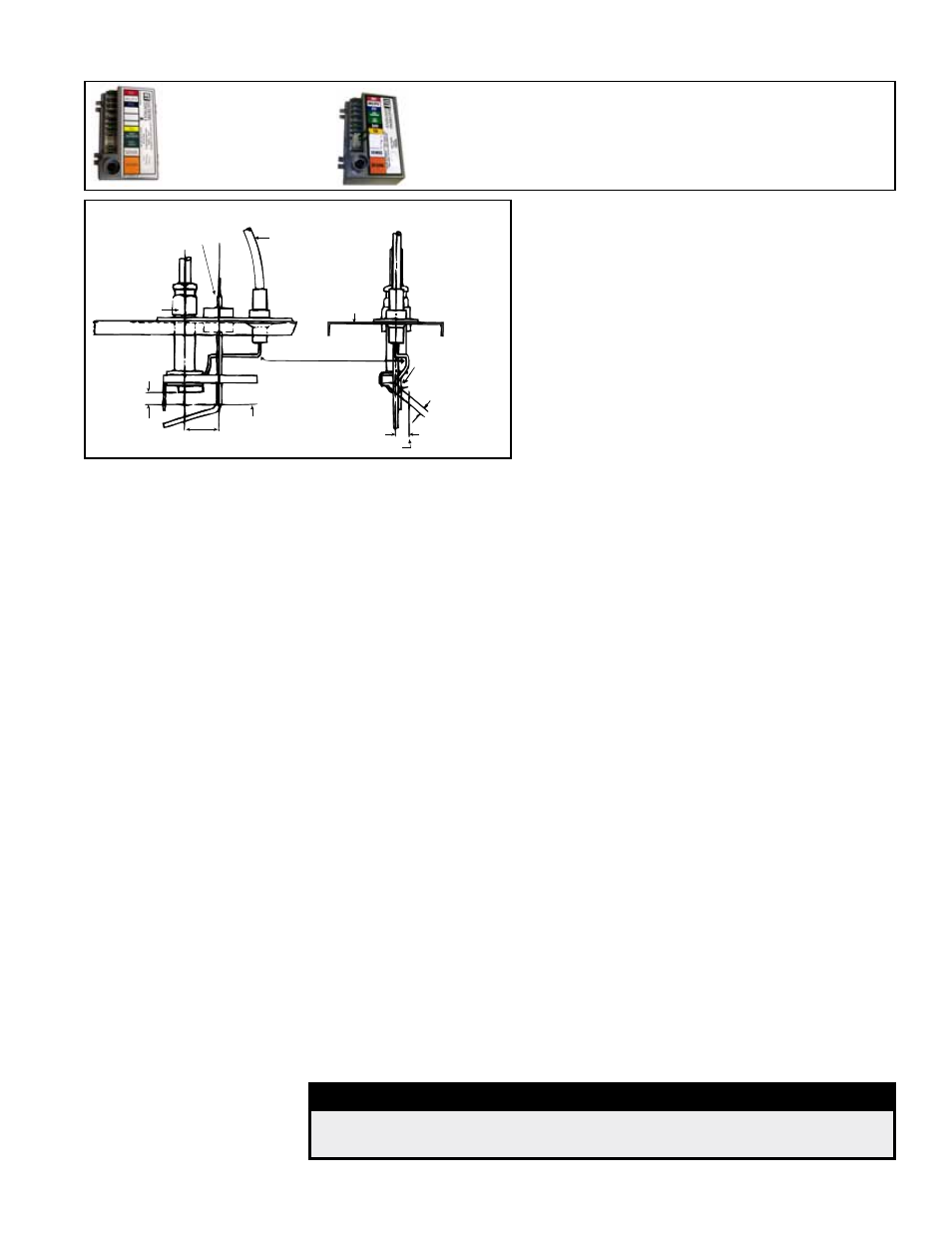
Service NOTE: If replacing an earlier model
of ignition controller, order replacement kit
P/N
257472 for a unit with recycling gas control
Option AH2 or
P/N 257473 for Option AH3 gas
control with lockout. (Option codes are listed on
the unit wiring diagram.)
Recycling Ignition
Controller, UTEC
1003-638A, P/N
257009, for Option
AH2 Gas Control
Ignition Controller
with Lockout, UTEC
1003-514, P/N 257010,
for Option AH3 Gas
Control
FIGURE 17 - Ignition Controller
Flame Sensing Probe
Pilot
Orifice
Centerline of
first burner
High Tension
Lead
Burner
Rack
Front
Spark Electrode
Spark Gap
7/64 (2.78mm)
TOP VIEW OF BURNER
TOP
VIEW
SIDE
VIEW OF
PILOT
1/4± 1/32
(6.38mm±.79)
23/32
(18.25mm)
7/16± 1/16
(11mm±1.6)
FIGURE 18 - Maintain spark gap of 7/64"
If no spark occurs, check the following:
a) Voltage between Terminals TH and 7 on the ignition
controller should be at least 20 volts and no higher
than 32 volts. Refer to Troubleshooting (Paragraph
10.3) if no voltage is observed.
b) Short to ground in the high tension lead and/or
ceramic insulator.
c) Pilot spark gap should be approximately 7/64".
NOTE: When checking for spark with the pilot burner
assembly removed from the burner rack, the pilot
assembly must be grounded to the heater for proper
spark.
If the above conditions are normal and no spark occurs,
replace the ignition controller.
If the main gas valve fails to open with a normal full size pilot flame established, check
for the following:
a) Voltage between black and brown leads on the main gas valve is 20 to 32 VAC
and there is no main gas flow with the built-in manual valve in FULL OPEN
position -- the main valve is defective.
b) No voltage between black and brown leads on the main gas valve -- check for
disconnected or shorted flame sensor lead or flame sensor probe.
When the above conditions are normal and the main gas flow is still off, the ignition
controller is probably defective.
8.6 Burners and
Carryover
System
These duct furnaces have individually formed steel burners with accurately die-formed
ports to give controlled flame stability without lifting or flashback with either natural or
propane gas. The burners are lightweight and factory mounted in an assembly which
permits them to be removed as a unit for inspection or service.
Natural gas burner racks (except when equipped with electronic modulation Option
AG39, AG40, AG41, or AG42; see Paragraph 8.4) are equipped with two flash car-
ryovers. Propane gas burners are equipped with one flash carryover and a regulated
gas lighter tube system.
During regular service, check the main burner ports, the carryover assemblies, and the
orifices for cleanliness.
8.7 Burner Air
Adjustment
Burner air shutters are not normally required on natural gas furnaces. Air shutters are
required on propane gas units and may require adjustment.
Before making any adjustments to the air shutters, allow the heater to operate for
about fifteen minutes with the air shutters open. The slotted screw on the end mani-
fold bracket moves the air shutters and adjusts all burners simultaneously. Turning
the screw clockwise opens the shutters; counterclockwise closes the shutters. After
the furnace has been in operation for 15 minutes, close the air shutters observing
the flame for yellow-tipping. Open the shutters until the yellow disappears. A limited
amount of yellow-tipping is permissible for liquefied petroleum gases. Natural gas
should not display any yellow-tipping.
When making the adjustment, close the air shutters no more than is necessary to elimi-
nate the problem condition.
DANGER
Failure to install and/or adjust air shutters according to directions
could cause property damage, personal injury, and/or death.