0 controls (cont'd), 4 gas controls (cont'd) – Reznor HRPD (Outdoor Duct Furnaces) Unit Installation Manual User Manual
Page 18
Form I-RP/HRPD, P/N 132210 R14, Page 18
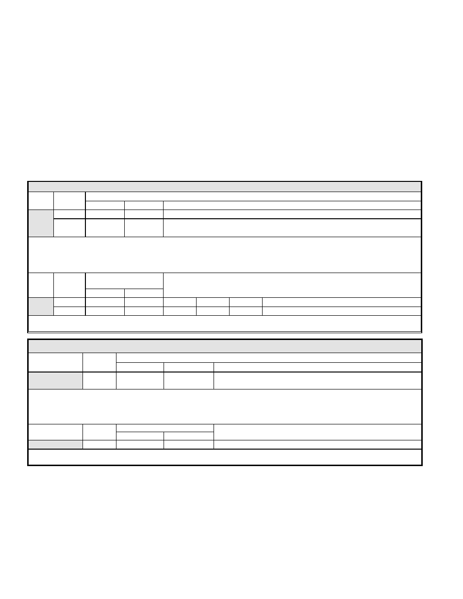
TABLE A - Recommended Settings for Staging Application - Options AG3 and AG15
Option
No. of
Furnaces
Ductstat Settings - Set
the Ductstat (See FIGURE 12A)
1st
2nd
Sequence of Staging with these settings
AG3
1
70°F
--
66°F High Stage ► 70°F Low Stage ► 74°F Shutdown
2
70°F
64°F
60°F High Stage Both Furnaces ► 64°F Low Stage 2nd Furnace ► 68°F Shutdown
2nd furnace ► 70°F Low Stage 1st furnace ► 74°F Shutdown 1st furnace
Option AG15 - Adjust the setpoint and the differential of the temperature selector (Johnson #A350). Adjust the offset
potentiometer on each of the stage adder modules (Johnson #S350). The settings listed below will provide the same sequence
of staging as shown above for Option AG3. Follow the manufacturer's instructions provided.
IMPORTANT: Set the temperature
selector and each stage adder module to "HEAT". Follow the wiring diagram to obtain proper sequencing.
Option
No. of
Furnaces
Temperature Selector
(A350)
Stage Adder (S350) Offset Settings (Refer to
FIGURE 13)
Setpoint
Differential
AG15
1
74°F
8°F
4°F
--
--
2
74°F
14°F
10°F
6°F
4°F
Operation: The differential setting and offset degrees allow the controls to adapt to any adjustment in temperature selection (50-
130°F).
ductstat setting, high fire is energized. Model HRPD includes two furnace sections and
each section is equipped with a two-stage gas valve. Set the ductstat (
FIGURE 12A or
13) as indicated in TABLE A, below.
The second method of multiple-stage makeup air operation is applicable only to
Model HRPD and is identified as Option AG4 or AG17. Each furnace in the package
is equipped with a single-stage gas valve. The single-stage gas valves are staged by
a two-stage ductstat. The furnaces are staged in sequence. This concept will achieve
two-stage control. Set the ductstat as indicated in
TABLE B.
The two types of ductstat control mechanisms used in these multiple-stage systems
are
either --
(1) the ductstat with temperature selector and attached capillary sensor is factory
installed (Option AG3 and AG4; see
FIGURE12A, or
(2) a sensing probe must be field installed in the heater discharge (See Paragraph
6.3.5). The sensing probe is wired to a remote, field-installed, electronic
temperature selector (
FIGURE 13).
8.0 Controls
(cont'd)
8.4 Gas Controls
(cont'd)
8.4.3 Optional Two-Stage Operation - Makeup Air (cont'd)
TABLE B - Recommended Settings for Staging Application - Options AG4 and AG17
Option
No. of
Furnaces
Ductstat Settings - Set
the Ductstat (See FIGURE 12A) i
1st
2nd
Sequence of Staging with this setting
AG4
2
70°F
--
66°F Full Rate Both Furnaces ► 70°F Shutdown 1st Furnace ►
74°F Shutdown 2nd furnace
Options AG17 - Adjust the setpoint and the differential of the temperature selector (Johnson #A350). Adjust the offset
potentiometer on each of the stage adder modules (Johnson #S350). The settings listed below will provide the same sequence
of staging as shown above for Option AG4. Follow the manufacturer's instructions provided.
IMPORTANT: Set the temperature
selector and each stage adder module to "HEAT". Follow the wiring diagram to obtain proper sequencing.
Option
No. of
Furnaces
Temperature Selector (A350)
Stage Adder (S350) Offset Settings
(Refer to illustration in
FIGURE 13)
Setpoint
Differential
AG17
2
74°F
8°F
4°F
Operation: The differential setting and offset degrees allow the controls to adapt to any adjustment in temperature selection (50-
130°F).
Optional Ductstat with Capillary Tubing (Options AG3 and AG4) - These makeup
air control options use a ductstat (See
FIGURE 12A) with an adjustable range from
0° to 100°F with a fixed differential of 3°. Due to different CFM settings and outside air
temperatures, the average downstream outlet temperature may not match the ductstat
setting exactly. After the installation is complete, re-adjust the setpoint of the duct-
stat to achieve the desired average discharge air temperature. In general, makeup air
applications are usually adjusted to discharge an outlet air temperature between 65°F
and 75°F.
Optional Ductstat with Electronic Remote Setpoint Module (Options AG15 and
AG17 ) - These two-stage makeup air options that are controlled from a sensing probe
with a remote electronic temperature selector that has a temperature operating range