0 mechanical, 1 gas piping and pressures – Reznor HRPD (Outdoor Duct Furnaces) Unit Installation Manual User Manual
Page 7
Form I-RP/HRPD, P/N 132210 R14, Page 7
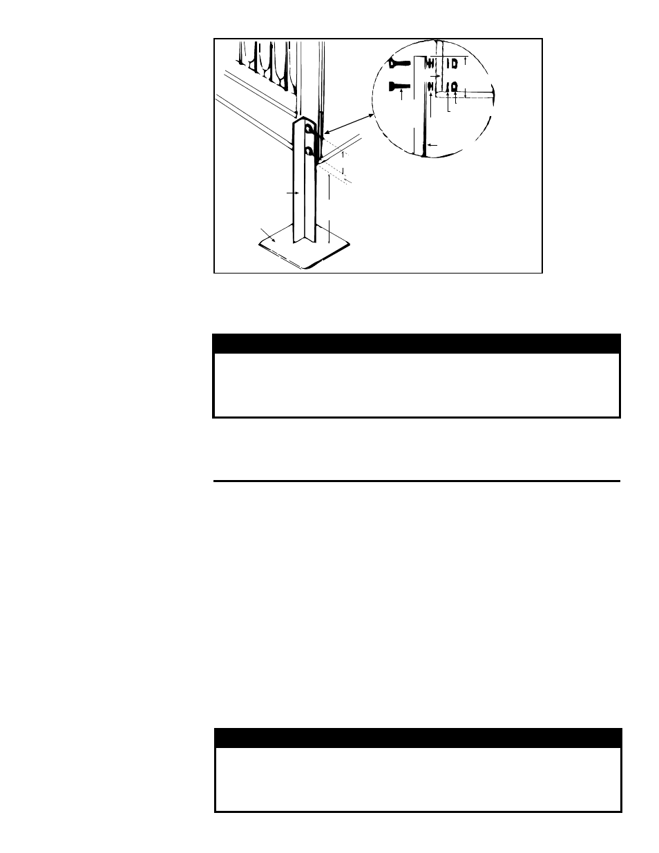
FIGURE 3 - Field-
Fabricated Supports
2 x 2 x 1/4
Angle Iron Leg
6 x 6 x 1/4
Metal Plate
Cabinet Leg
A
4 (102mm)
2-1/4
(57mm)
Cabinet Leg
1/4 Nuts
Lockwashers
Spacers
1/4 x 1-1/2
Hex Head
Bolts
Angle Iron Leg
Drill 9/32 clearance
holes in angle iron
leg and cabinet leg.
A = 3 (76mm) minimum height for
clearance to combustibles. The recommended
height is 8 (203mm) for plumbing and service.
7
(178mm)
NOTE: Drawing is not
proportional; comply with
dimensions as written.
All piping must be in accordance with requirements outlined in the National Fuel Gas
Code NFPA54/ANSI Z223.1 (latest edition) or CSA-B149.1 (latest edition) Natural Gas
and Propane Installation Code. Gas supply piping installation should conform with
good practice and with local codes.
Duct furnaces for natural gas are orificed for operation with gas having a heating value
of 1000 (+ or - 50) BTU per cubic ft. If the gas at the installation does not meet this
specification, consult the factory for proper orificing.
Pipe joint compounds (pipe dope) shall be resistant to the action of liquefied
petroleum gas or any other chemical constituents of the gas being supplied.
Install a ground joint union and manual shutoff valve upstream of the unit control sys-
tem, as shown in
FIGURE 4A. The 1/8" plugged tapping in the shutoff valve provides
connection for supply line pressure test gauge. The National Fuel Gas Code requires
the installation of a trap with a minimum 3" drip leg. Local codes may require a mini-
mum drip leg longer than 3" (typically 6").
After all connections are made, disconnect the pilot supply at the control valve and
bleed the system of air. Reconnect the pilot line and leak-test all connections by brush-
ing on a soap solution.
WARNING
All components of a gas supply system must be leak tested prior
to placing equipment in service. NEVER TEST FOR LEAKS WITH
AN OPEN FLAME. Failure to comply could result in personal
injury, property damage or death.
6.0 Mechanical
WARNING
This appliance is equipped for a maximum gas supply pressure
of 1/2 psi, 3.4 kPa, or 14 inches water column. Supply pressure
higher than 1/2 psi requires installation of an additional service
regulator external to the unit.
PRESSURE TESTING SUPPLY PIPING
Test Pressures Above 1/2 PSI: Disconnect the heater and manual valve from the
gas supply line which is to be tested. Cap or plug the supply line.
Test Pressures Below 1/2 PSI: Before testing, close the manual valve on the heater.
6.1 Gas Piping and Pressures