Reznor HRPD (Outdoor Duct Furnaces) Unit Installation Manual User Manual
Page 11
Form I-RP/HRPD, P/N 132210 R14, Page 11
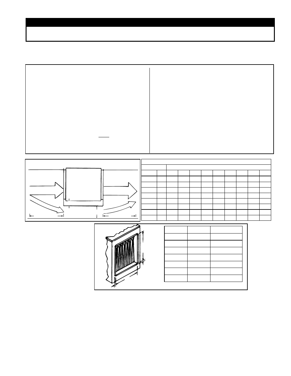
When the CFM of air throughput is greater than desirable or permissible for the unit,
a bypass duct may be constructed. Follow these instructions to determine the correct
size of the bypass duct.
6.3.3 Constructing a
Bypass Duct
Top View
of Furnace
Control Side
Bypass Duct A
2 (51mm) minimum
18 (457mm)
18 (457mm)
FIGURE 7 - Bypass Duct
Bypass CFM
"A" Width
Pressure Drop through the Furnace
inches mm
0.10 0.15 0.20 0.25 0.30 0.35 0.40 0.45 0.50
3"
76
490 530 610 700 780 830 900 960 1010
4"
102 630 750 870 980 1090 1160 1250 1310 1400
5"
127 850 1010 1190 1300 1410 1520 1640 1730 1810
6"
152 1050 1290 1480 1650 1800 1940 2090 2200 2320
7"
178 1250 1510 1760 1960 2180 2320 2500 2650 2800
8"
203 1490 1810 2100 2350 2560 2760 2940 3110 3290
9"
229 1700 2100 2400 2700 2970 3200 3400 3600 3800
10"
254 1920 2350 2760 3090 3650 4020 4300 4550 4800
Directions for Sizing Bypass Duct
1) From the tables in on page 10, find the pressure drop
(P.D.) and the allowable CFM for the furnace that is
being installed.
Example: Standard Size RP150 @ 50°F temperature
rise - P.D. .38; CFM 2210
2) Subtract the allowable CFM from the actual CFM of
the installation to determine how much air must be
diverted through the bypass duct.
Example: Blower CFM 3000
Allowable CFM -2210
Bypass CFM 790
3) Go to the column in the Bypass CFM Chart that is
closest to the pressure drop through the heater. Move
down in that column until you find the CFM closest to
the answer in Step 2).
Example: P.D. .40; Bypass CFM 900
4) Move to the left column to find out the required size
of the bypass duct.
Example: Bypass Duct Size is 3"
Depth of the bypass duct is 18" on both inlet and outlet
ends. Bypass duct must be located on side opposite
controls and 2" from the heat exchanger side panel.
NOTE: Not all capacities are covered in this chart. If
your installation is not covered, the correct size may be
determined by consulting the factory representative.
6.3.4 Duct
Connections
G
3/4 (19)
3/4 (19)
18
(457)
RP
HRPD
G
75, 100
--
12-1/2 (318)
125
250
15-1/4 (387)
150, 175
300, 350
20-3/4 (527)
200, 225
400
26-1/4 (667)
250, 300
500, 600
34-1/2 (876)
350
700
40 (1016)
400
800
45-1/2 (1156)
FIGURE 8 - Duct
Connection
Dimensions for
Horizontal Discharge -
inches (mm)
WARNING
The furnace must be installed on the positive pressure side of the air-circulating blower.
See Hazard Levels, page 2.
Requirements and
Suggestions for
Connecting and
Installing Ducts
•
Type of Ductwork - The type of duct installation to be used depends in part on the
type of construction of the roof (whether wood joist, steelbar joist, steel truss, pre-
cast concrete) and the ceiling (hung, flush, etc.).
•
Ductwork Material - Rectangular duct should be constructed of not lighter than
No. 26 U.S. gauge galvanized iron or No. 24 B & S gauge aluminum.
•
Ductwork Structure - All duct sections 24 inches (610mm) or wider, and over 48
inches (1219mm) in length, should be cross broken on top and bottom and should
have standing seams or angle-iron braces. Joints should be S and drive strip, or
locked.
•
Through Masonry Walls - No warm air duct should come in contact with masonry
walls. Insulate around all air duct through masonry walls with not less than 1/2" (1"
recommended) of insulation.