0 mechanical (cont'd), 1 gas piping and pressures (cont'd) – Reznor HRPD (Outdoor Duct Furnaces) Unit Installation Manual User Manual
Page 8
Form I-RP/HRPD, P/N 132210 R14, Page 8
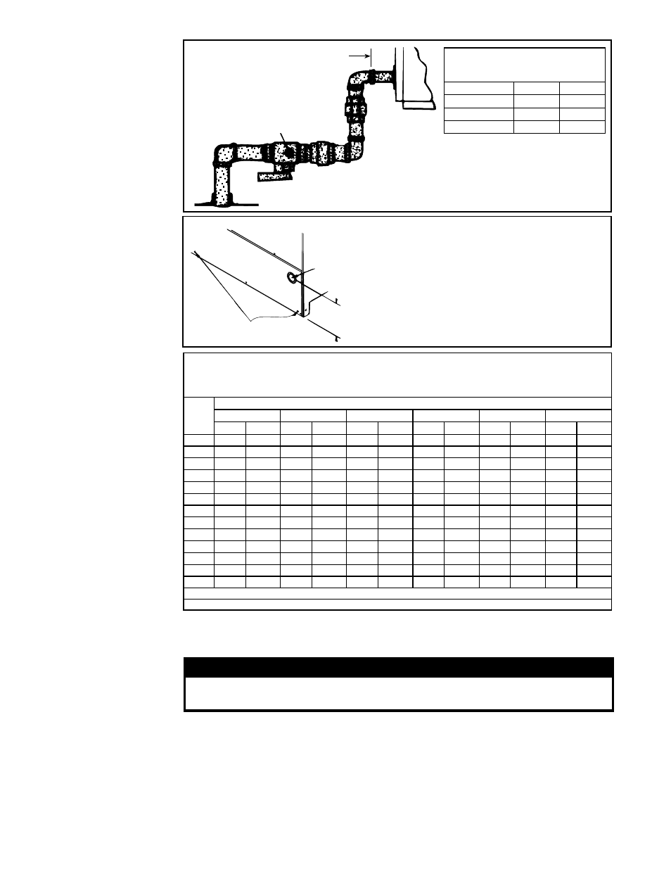
Minimum 1 (25mm) clearance
between heater access panel
and elbow or fitting
Install a 1/8 NPT plug
with tap for test gauge
immediately upstream
of the gas supply
connection.
Manual shutoff valve
Installer supplies
manual shutoff,
ground unions
and shaded piping
FIGURE 4A -
Gas Connection
Requirements
Gas Supply Sizing
Measuring manifold gas pressure cannot be done until the heater is in operation. It is
included in the steps of the "Check-Test-Start" procedure in Paragraph 9.0 The following
warnings and instructions apply.
WARNING
Manifold gas pressure must never exceed 3.5" w.c. for natural gas
and 10" w.c. for propane gas.
For Natural Gas: When the heater leaves the factory, the combination valve is set so that
the outlet gas pressure of a single-stage valve or high fire of a two-stage valve is regulated
to 3.5" w.c. Low fire on a two-stage valve is set to 1.8" w.c. Inlet supply pressure to the
valve must be a minimum of 5" w.c. or
as noted on the rating plate and a maximum of
14" w.c.
NOTE: Always check the rating plate for minimum gas supply pressure.
Minimum supply pressure requirements vary based on size of burner and the gas control
option. Most units require a minimum of 5" w.c. of natural gas as stated above, but Sizes
350 and 400 with electronic modulation require a minimum of 6" w.c. natural gas supply
pressure. Sizes 300 and 350 with mechanical modulation require 7" w.c.
FIGURE 4B - Gas
Connection Location
- Model Series RP
and HRPD (Multiple
furnaces require
one connection;
see FIGURE 2B
for approximate
location.)
Gas Supply
Entrance
5
-3/4
(146mm)
Condensate
Weep Holes
Install the gas supply piping so that
when the union is disconnected, the
supply pipe will not interfere with
the removal of the burner rack. (The
burner rack slides out of the control
side of the furnace.)
Manifold or Orifice
(Valve Outlet)
Pressure Settings
6.0 Mechanical
(cont'd)
6.1 Gas Piping
and Pressures
(cont'd)
Gas Connection to Single-Stage
Valve (Not Gas Supply Line Size)
RP
75-250 300-400
HRPD
250-500 600-800
Natural Gas
1/2"
3/4"
Propane
1/2"
1/2"
Capacity of Piping
Cubic Feet per Hour based on 0.3" w.c. Pressure Drop
Specific Gravity for Natural Gas -- 0.6 (Natural Gas -- 1000 BTU/Cubic Ft)
Specific Gravity for Propane Gas -- 1.6 (Propane Gas -- 2550 BTU/Cubic Ft)
Length
Diameter of Pipe
of
1/2"
3/4"
1"
1-1/4"
1-1/2"
2"
Pipe
Natural Propane Natural Propane Natural Propane Natural Propane Natural Propane Natural Propane
20'
92
56
190
116
350
214
730
445
1100
671
2100
1281
30'
73
45
152
93
285
174
590
360
890
543
1650
1007
40'
63
38
130
79
245
149
500
305
760
464
1450
885
50'
56
34
115
70
215
131
440
268
670
409
1270
775
60'
50
31
105
64
195
119
400
244
610
372
1105
674
70'
46
28
96
59
180
110
370
226
560
342
1050
641
80'
43
26
90
55
170
104
350
214
530
323
990
604
90'
40
24
84
51
160
98
320
195
490
299
930
567
100'
38
23
79
48
150
92
305
186
460
281
870
531
125'
34
21
72
44
130
79
275
168
410
250
780
476
150'
31
19
64
39
120
73
250
153
380
232
710
433
175'
28
17
59
36
110
67
225
137
350
214
650
397
200'
26
16
55
34
100
61
210
128
320
195
610
372
Note: When sizing supply lines, consider possibilities of future expansion and increased requirements.
Refer to National Fuel Gas Code for additional information on line sizing.