Power operations, Power inputs, Power priority – RED DSMC POWER User Manual
Page 8: Red dsmc power operation guide
COPYRIGHT © 2014 RED.COM, INC
RED DSMC POWER OPERATION GUIDE
955-0038, REV-F
|
8
POWER OPERATIONS
This section describes the basic power operations of the DSMC system.
For more information, see the
, available at
.
WARNING: Modules, displays, and accessories are NOT HOT SWAPPABLE, meaning that you cannot remove or
install the item while the camera is turned on. Before installing or removing a module, display, or accessory,
you MUST turn off the camera. Failure to do so may result in damage to the item or DSMC that is not covered
under warranty.
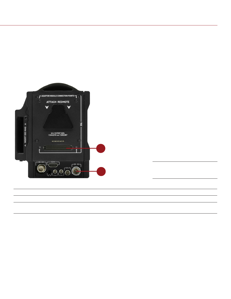
POWER INPUTS
1
2
There are two (2) primary power inputs that provide power to the DSMC BRAIN:
#
DSMC POWER INPUT
DESCRIPTION
1
SEARAY power connector
Provides power to the BRAIN from attached DSMC modules
2
DC IN connector
Provides power to the BRAIN using a AC Power Adaptor (DSMC) or
certain battery modules, such as the Backpack Quickplate (Short)
NOTE: Additionally, one (1) REDVOLT
®
battery may be used in conjunction with the DSMC Side Handle to provide
short term power and support hot-swapping of other power sources.
POWER PRIORITY
When multiple power sources are connected to the BRAIN, power consumption is prioritized in this sequence:
1. DC power supply (DC IN connector)
2. Attached RED BRICK
®
(Lowest state of charge first)
3. Battery module batteries (SEARAY connector; lowest state of charge first)
4. REDVOLT battery in an attached DSMC Side Handle
SEARAY Connector (top) and
DC IN Connector (bottom)