Install the redvolt xl module, Redvolt xl module switch plate, Red dsmc power operation guide – RED DSMC POWER User Manual
Page 31
RED DSMC POWER OPERATION GUIDE
COPYRIGHT © 2014 RED.COM, INC
955-0038, REV-F
|
31
INSTALL THE REDVOLT XL MODULE
The REDVOLT XL Module is designed with a reversible switch plate, enabling direct installation to the DSMC
BRAIN or mounting to other modules.
For more information on installing and removing the REDVOLT XL Module, go to:
“DSMC Adaptor Operations” on page 21
“DSMC Power Module Operations” on page 23
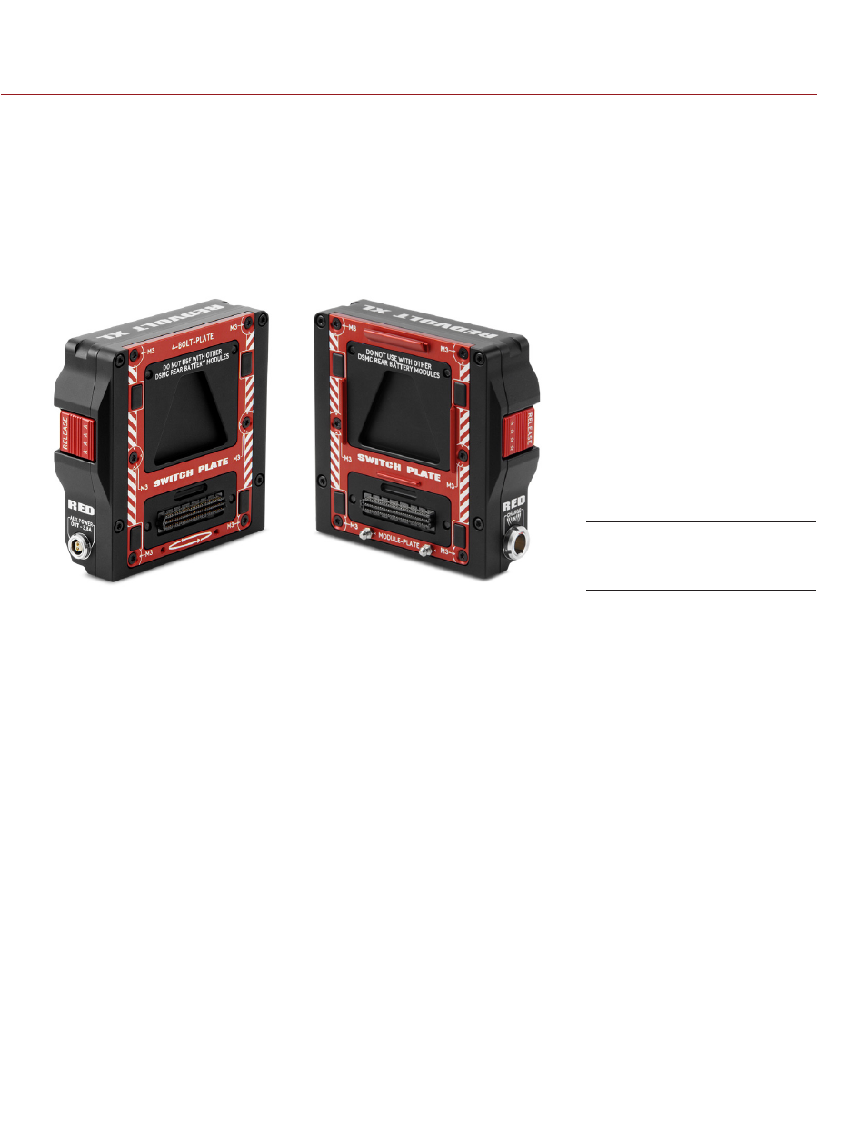
REDVOLT XL MODULE SWITCH PLATE
To configure the switch plate for different mounting variations, follow the instructions below:
1. Loosen the six (6) M3x0.5 x 8 mm screws attaching the SWITCH PLATE evenly using a T10 Torx driver.
2. Remove the six (6) screws. DO NOT discard screws.
3. Install the switch plate to the desired mounting configuration:
‒ 4-BOLT-PLATE (Left image): Supports attachment directly to DSMC.
‒ MODULE PLATE (Right Image): Supports attachment to DSMC modules.
4. Insert and tighten the six (6) M3x0.5 x 8 mm screws evenly. DO NOT FULLY TIGHTEN.
5. Fully tighten the six (6) M3x0.5 x 8 mm screws evenly. DO NOT exceed 70 in-oz, or damage may occur. DO
NOT OVERTIGHTEN.
For more information, see the
, available at
NOTE: For more information or replacement screws, please contact your Bomb Squad representative.
REDVOLT XL Module Switch
Plate