Menu display features, Overview, Menu display – PRG S400 User Manual 3.1 User Manual
Page 45: Features, 208v
PRG SERIES 400
®
POWER AND DATA DISTRIBUTION SYSTEM USER MANUAL
39
MENU DISPLAY FEATURES
Overview
The Menu Display, located on each Rack Breaker Module, is used to configure, test and access internal status
information for the PRG Series 400 Comm System. The soft-programmable buttons are used with the dynamic menu
options, while the Reset button performs a hard rest of the module’s processor.
Note: Pressing the Reset button may interrupt any DMX512 universes on the network briefly, since the switch will
also go into a reset state while the button is held down.
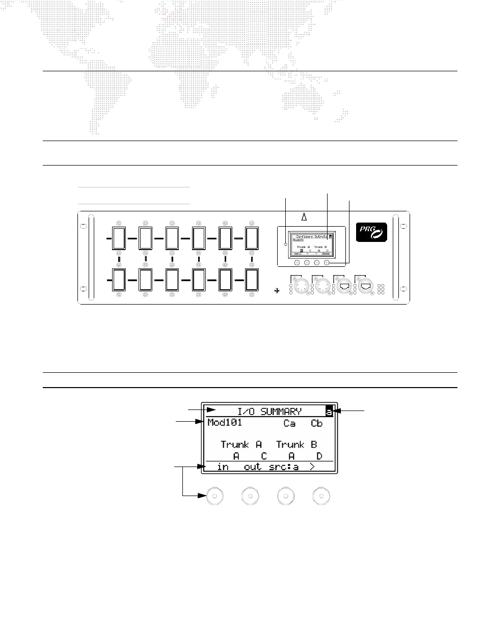
Figure 3-1: Menu Display Controls
The top line of the window displays the title of the current menu, while the center section displays the menu-specific
information. The bottom line provides the button functions applicable to that particular menu page. The right arrow (>)
symbol in the last button position indicates that there are more options available. These options will cycle through as
the right arrow (>) button is pressed.
Note: The buttons will auto-repeat if held down.
Figure 3-2: Menu Layout
XØ-YØ
208V
15A x 6
CIRCUIT
TRUNK
B
TRUNK
15A x 6
CIRCUIT
208V
A
1
ZØ-XØ
YØ-ZØ
XØ-YØ
2
3
4
DMX
YØ-ZØ
ZØ-XØ
RDM Tx
RDM Rx
INPUT 1
DMX Rx
5
6
RESET
208V
DISTRIBUTION
ETHERNET
INPUT 2
PORT 1
PORT 2
Rx
Tx
B
A
SYSTEM
DATA
TRUNK
LINK
15A x 12 CIRCUITS
MODEL 20-9680-2915
S-400
POWER / DATA
Menu
Soft-Programmable
15A 208V MODEL SHOWN
Rack Components May Vary
Display
Hard Reset
Button
Buttons
Current Menu Title
Menu-Specific Information
Applicable Button Functions
Current Source