Breaker module, 208v – PRG S400 User Manual 3.1 User Manual
Page 21
PRG SERIES 400
®
POWER AND DATA DISTRIBUTION SYSTEM USER MANUAL
15
Breaker Module
The Breaker Module provides two trunk outputs, with each circuit protected by an individual circuit breaker, for the
purpose of routing power and control to the system. The total number of circuits depends on the model. The module
accepts 100BaseT Ethernet and DMX512 inputs, and features a Menu Display which provides control and
configuration of the signal routing to all connected Breakout components. The Breaker Module is installed directly into
the Rack unit.
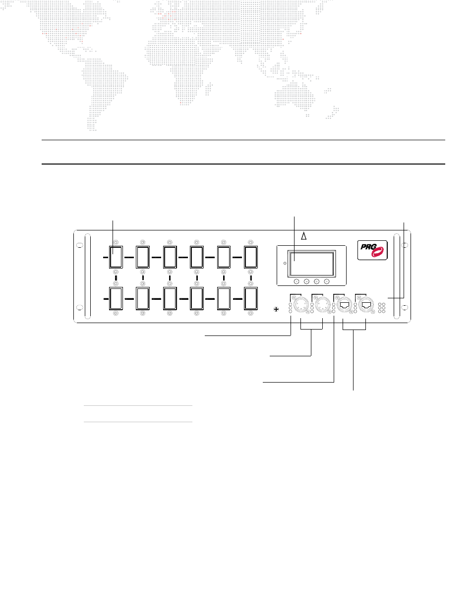
The following illustration provides a detailed description of Breaker Module connections, controls and indicators.
Note: The 15A 208V model is shown here, however, these components are typical of all Breaker Module models
except the Soca Output Breaker Module (which is shown on the following page).
Figure 1-10: Breaker Module Connections, Controls and Indicators
Model Configurations
Several Breaker Module configurations are available, based on power requirements:
+
12-Channel 15A 120V Module
+
12-Channel 15A 208V Module
+
6-Channel 30A 208V Module
+
8-Channel 15/30A 208V Module (mixed)
208V
6
DISTRIBUTION
POWER / DATA
TRUNK
DATA
ETHERNET
SYSTEM
S-400
Tx
LINK
Rx
XØ-YØ
YØ-ZØ
ZØ-XØ
CIRCUIT
TRUNK
CIRCUIT
15A x 6
B
208V
15A x 6
A
208V
TRUNK
1
2
3
INPUT 1
INPUT 2
PORT 1
PORT 2
A B
ZØ-XØ
XØ-YØ
YØ-ZØ
MODEL 20-9680-2915
15A x 12 CIRCUITS
4
5
RESET
RDM Rx
DMX Rx
RDM Tx
DMX
Menu Display - used to configure, test,
and access internal status information for
the Series 400 Rack system using
associated soft-programmable buttons.
Circuit Breaker Switch (12) - provides
individual protection for the connected luminaire.
Ethernet Connectors (Ports 1 & 2) - allows
Ethernet connection to system. Accepts
standard Ethernet or Neutrik® EtherCon®
connectors.
DMX Input Connectors (1 & 2) - DMX512
in from console or controller.
DMX LEDs - indicates valid DMX512
receive, RDM receive and transmit when lit.
Ethernet LEDs - indicates valid Ethernet
link, transmit and receive when lit.
Trunk LEDs (A & B) -
indicates valid Trunk cable
data link and data flow.
15A 208V MODEL SHOWN
Rack Components May Vary