System installation and power up, Load distribution – PRG S400 User Manual 3.1 User Manual
Page 32
26
PRG SERIES 400
®
POWER AND DATA DISTRIBUTION SYSTEM USER MANUAL
SYSTEM INSTALLATION AND POWER UP
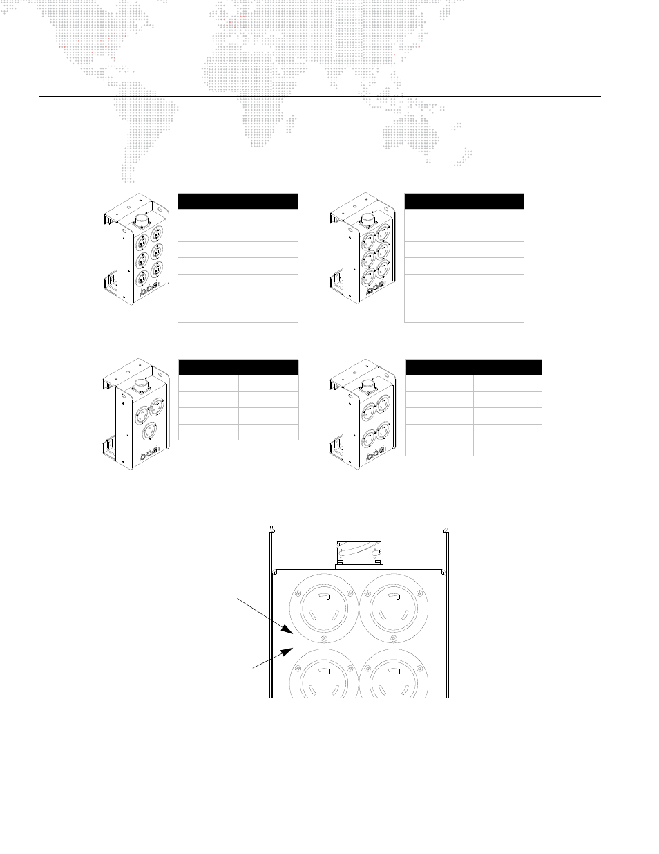
Load Distribution
Consideration for proper load distribution should be followed when connecting devices. Be sure to evenly distribute
the load across the phases. Refer to the following charts.
For convenience, these phase specifications are printed on the front panel of each Breakout Box.
Figure 2-1: Phase Specifications
15A 208V Breakout Box
Connector
Phase
1
X - Y
2
Y - Z
3
Z - X
4
X - Y
5
Y - Z
6
Z - X
15A 120V Breakout Box
Connector
Phase
1
X - N
2
Y - N
3
Z - N
4
X - N
5
Y - N
6
Z - N
30A 208V Breakout Box
Connector
Phase
1
X - Y
2
Y - Z
3
Z - X
15A/30A Mixed Breakout Box
Connector
Phase
1 (15A)
X - Y
2 (15A)
X - Y
3 (30A)
Y - Z
4 (30A)
Z - X
4
1
15A x 6
208V
MODEL
20-9680-6615
XØ-YØ
XØ-YØ
Phases Loaded
Connector Number