Figure 2-12, Power and data distribution system user manual, Rack components may vary – PRG S400 User Manual 3.1 User Manual
Page 38
32
PRG SERIES 400
®
POWER AND DATA DISTRIBUTION SYSTEM USER MANUAL
Notes:
+
When properly connected, a click inside the Breaker Module will be heard as the Trunk Cable key engages.
+
When properly connected, the green Trunk Data LINK indicator will be lit.
+
Connecting or disconnecting an A/B Switch while the system is powered up can cause an apparent switch
closure resulting in a change to the source system.
+
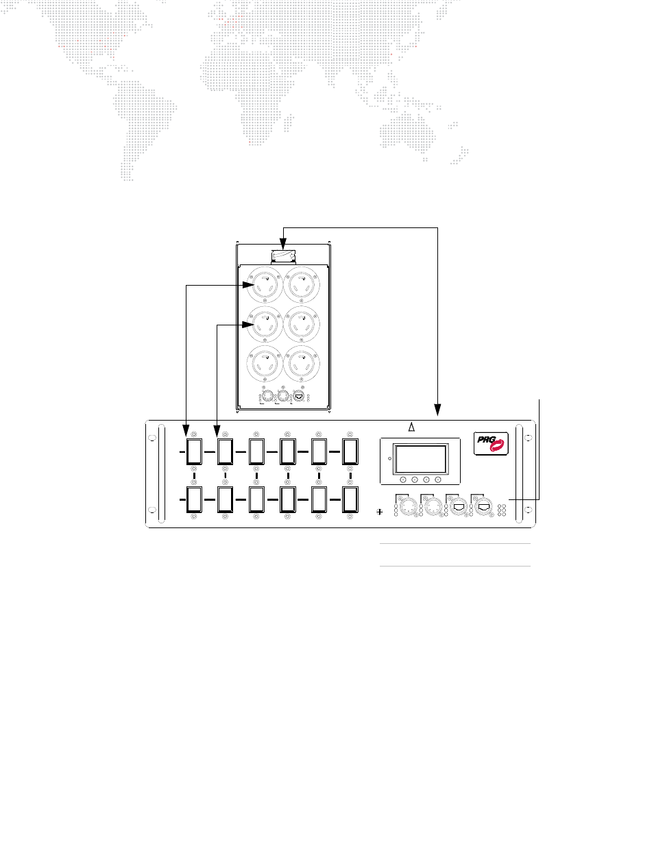
Connector numbers on the Breakout Boxes correspond to breaker switch numbers on the associated Breaker
Module. A Breakout Box connected to TRUNK A corresponds to the breaker switches for Trunk Circuit A, while a
Breakout Box connected to TRUNK B corresponds to the breaker switches for Trunk Circuit B. Refer to the
following diagram:
Figure 2-12: Breaker Switch and Connector Numbering Scheme
208V
6
DISTRIBUTION
POWER / DATA
TRUNK
DATA
ETHERNET
SYSTEM
S-400
Tx
LINK
Rx
XØ-YØ
YØ-ZØ
ZØ-XØ
CIRCUIT
TRUNK
CIRCUIT
15A x 6
B
208V
15A x 6
A
208V
TRUNK
1
2
3
INPUT 1
INPUT 2
PORT 1
PORT 2
A B
ZØ-XØ
XØ-YØ
YØ-ZØ
MODEL 20-9680-2915
15A x 12 CIRCUITS
4
5
RESET
RDM Rx
DMX Rx
RDM Tx
DMX
Trunk Data LEDs (A & B)
indicates valid Trunk cable
data link and data flow.
3
2
6
5
4
1
CIRCUIT USE
FOR BRANCH
ONLY
POWER / DATA
SYSTEM
DISTRIBUTION
S-400
15A x 6
208V
DMX Rx
RDM Tx
RDM Rx
DMX 1
DMX 2
ETHERNET
DATA
TRUNK
Tx
Rx
LINK
MODEL
20-9680-6615
XØ-YØ
XØ-YØ
YØ-ZØ
YØ-ZØ
ZØ-XØ
ZØ-XØ
Breaker Switch 1 corresponds
to Connection 1 on Breakout Box,
Switch 2 corresponds to
Connection 2, etc.
BREAKOUT BOX
BREAKER MODULE
Trunk connection to
TRUNK A at rear of
Breaker Module
15A 208V MODELS SHOWN
Rack Components May Vary