Figure 2-4 ), Must be used, Always – PRG S400 User Manual 3.1 User Manual
Page 34: Power and data distribution system user manual
28
PRG SERIES 400
®
POWER AND DATA DISTRIBUTION SYSTEM USER MANUAL
Step
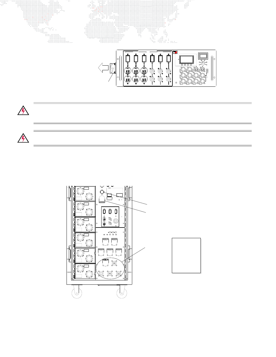
8. Connect console and other auxiliary devices to Front of House Breakout Box. Refer to
on page 18 for detailed connection diagram.
Figure 2-4: FOH Module Trunk Connection
WARNING:
A 400 Amp Disconnect
must be used
when house service is greater than 400 amps and more
than 10 feet from rack. 4/Ø feeders are rated for 400 amps or less. It is recommended that a PRG Series 400
400 Amp Disconnect be used. Refer to the Series 400 400 Amp Disconnect User Manual (02.9680.0200).
WARNING:
Ensure house service mains breaker and rack Master Switch are OFF before connecting mains
power cables to rack. Ground should
always
be connected first.
Step
9. At house service mains breaker (or 400 Amp Disconnect), turn power OFF.
Step 10. At Series 400 Rack, ensure Master Switch is OFF. To disengage Master Switch, pull down red protective
cover and press red button (Figure 2-5).
Step 11. Connect mains power cable Cam-Loks in the following order:
1) Ground, 2) Neutral 3) X Phase, 4) Y Phase, and 5) Z Phase.
Figure 2-5: Disengaging Master Switch and Connecting Cam-Loks
Step 12. Proceed to next section for Power Up instructions.
10
11
RESET
PORT 1
PORT 2
ETHERNET
Z-N
X-N
Y-N
DMX
TRUNK
DATA
LINK
Rx
Tx
Z-X
Y-Z
X-Y
FRONT of HOUSE MODULE
MODEL 20-9680-8615
6
AC LINE VOLTS
208V/15A
XØ-N
YØ-N
ZØ-N
XØ-YØ
YØ-ZØ
120V/15A
1
FOR BRANCH CIRCUIT USE ONLY
2
3
4
5
DMX INPUTS
ZØ-XØ
3
7
DMX Rx
RDM Rx
RDM Tx
RDM Tx
8
4
RESET
1
RDM Rx
DMX Rx
DMX Rx
RDM Tx
RDM Rx
2
DMX
9
5
Trunk Connector
TO FOH BREAKER MODULE
Master Switch ON Button
Master Switch OFF Button
(under red protective cover)
Cam-Lok Input CONNECTION
1) Ground
2) Neutral
3) X Phase
4) Y Phase
5) Z Phase
ORDER:
Connectors