Component and power connections – PRG S400 User Manual 3.1 User Manual
Page 33
PRG SERIES 400
®
POWER AND DATA DISTRIBUTION SYSTEM USER MANUAL
27
Component and Power Connections
For examples of basic system configurations, refer to
Use the following procedure to connect rack components:
Step
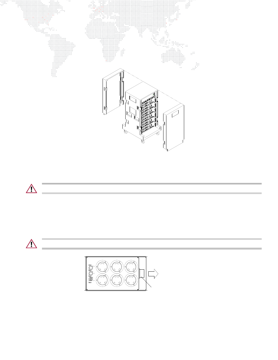
1. Place rack in desired location and remove front and back covers (Figure 2-2).
Figure 2-2: Removing Rack Covers
Step
2. Turn OFF all breakers at Rack and Breakout Boxes.
Step
3. Turn OFF Mater Switch.
CAUTION:
Always use safety cables when installing Breakout Boxes in truss.
Step
4. Install Breakout Boxes in truss or other location near fixtures. Refer to
"Breakout Box Mounting Options"
page 33 for mounting options. Attach safety cable.
Step
5. Connect appropriate length Trunk Cables to Breakout Box trunk connectors and route towards rack
Step
6. Connect required fixtures and data devices to Breakout Boxes. Refer to
detailed connection diagram.
CAUTION:
Evenly distribute the load across phases. Refer to
Figure 2-3: Breakout Box Trunk Connection
Step
7. If required, place Front of House Breakout Box near lighting control console. Connect appropriate length
Trunk Cable to trunk connector and route towards rack (Figure 2-4).
Trunk Connector
TO BREAKER MODULE