Breakout box – PRG S400 User Manual 3.1 User Manual
Page 23
PRG SERIES 400
®
POWER AND DATA DISTRIBUTION SYSTEM USER MANUAL
17
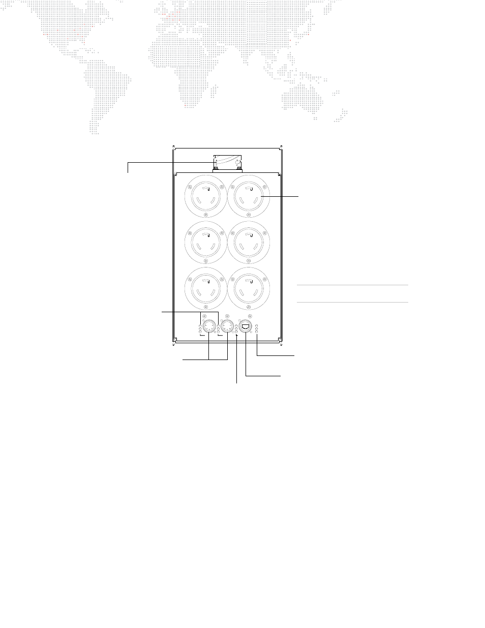
Breakout Box
The Breakout Box supplies power and control signal for three, four or six devices, depending on the model. LEDs
provide verification of the power and data signals. The Breakout Box can be installed in a truss with a choice of
several mounting hardware options, providing a convenient location for connecting system devices.
The following illustration provides a detailed description of the Breakout Box connections, indicators and mounting
hardware options. (The 15A 208V model is shown here, however, these components are typical of all Breakout Box
models.)
Figure 1-12: Breakout Box Connections and Indicators
Model Configurations
Several Breakout Box configurations are available, based on power requirements:
+
6-Channel 15A 120V Module
+
6-Channel 15A 208V Module
+
3-Channel 30A 208V Module
+
4-Channel 15/30A 208V Module (mixed)
3
2
6
5
4
1
CIRCUIT USE
FOR BRANCH
ONLY
POWER / DATA
SYSTEM
DISTRIBUTION
S-400
15A x 6
208V
DMX Rx
RDM Tx
RDM Rx
DMX 1
DMX 2
ETHERNET
DATA
TRUNK
Tx
Rx
LINK
MODEL
20-9680-6615
XØ-YØ
XØ-YØ
YØ-ZØ
YØ-ZØ
ZØ-XØ
ZØ-XØ
Trunk Connector -
provides trunk cable
connection (from
Breaker Module).
Power Output Connector (6) -
provides AC power to devices.
DMX Out (2) - provides
two DMX512 universes for local
devices. (Universes selectable
at Series 400 Rack.)
Trunk LEDs - indicates valid Trunk cable
data link, transmit and receive when lit.
Ethernet LEDs - indicates
valid Ethernet link, transmit
and receive when lit.
Ethernet Port - accepts standard Ethernet or
Neutrik® EtherCon® connectors.
DMX LEDs - indicates
valid DMX512 receive,
RDM receive and
transmit when lit.
15A 208V MODEL SHOWN
Rack Components May Vary