Installing an ethernet switch, Both, Only – PRG S400 User Manual 3.1 User Manual
Page 35
PRG SERIES 400
®
POWER AND DATA DISTRIBUTION SYSTEM USER MANUAL
29
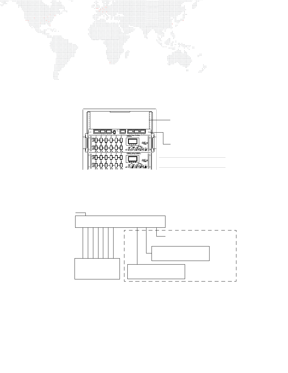
Installing an Ethernet Switch
A Series 400 Ethernet Switch can be used independently or installed directly in a Series 400 rack chassis, using any
blank space above the LED Meter Module.
To install in Series 400 rack:
Step
1. Install Ethernet Switch as required in top portion of rack chassis (Figure 2-6).
Step
2. At Ethernet Switch rear panel, connect AC Line Cord 208V PowerCon® Cable (supplied) to Neutrik®
connector.
Step
3. After power is applied, verify that ON indicator is lit.
Step
4. At front panel, connect data cables as required.
Figure 2-6: Additional Rack Space
The Series 400 10-Port Ethernet Switch connects Ethernet devices using
both
CAT5e copper wire
and
armored fiber
optic cable. Copper wire communication ports conform to 10/100Base-Tx standards and the fiber ports conform to
10/100Base-Fx standards. The Series 400 7-Port Ethernet Switch connects Ethernet devices using
only
CAT5e
copper wire.
Figure 2-7: Ethernet Switch Connection Options
3U of rack space for
adding additional signal
processing devices.
EXAMPLE CONFIGURATION
S400 Rack Components May Vary
LED Meter Module
AC Input
Fiber Optic Out to Additional Switches
1
0
/1
00B
ase-T
1
0
/1
00B
ase-T
1
0
/1
00B
ase-T
1
0
/1
00B
ase-T
1
0
/1
00B
ase-T
1
0
/1
00B
ase-T
1
0
/1
00B
ase-T
F
iber Op
tic
F
iber Op
tic
Virtuoso Nodes
or
Any Ethernet Device
(up to 7)
SERIES 400 ETHERNET SWITCH
Input from
a Virtuoso Console
or another switch
Input from
a Virtuoso Console
or another switch
10-Port Model Only