Potter PFC-6075 User Manual
Page 47
3-41
PFC-6075 • 5403593 • Rev C • 2/13
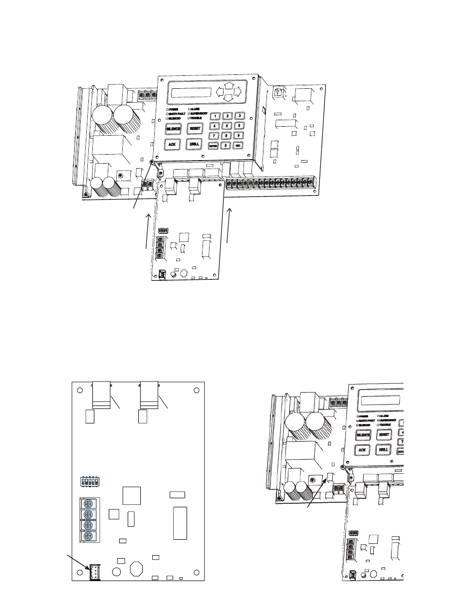
The UD-1000 slides into the guides located at the bottom of the panel, and then secured with screws as shown in the following
illustration.
Example of an Installed UD-1000 Dialer
Figure 55.
P-Link & Dip Switch Locations
The UD-1000 is connected to the P-Link bus. A four-wire cable (P/N 5210514) is supplied with the UD-1000, which should be
used to connect the P1 on the UD-1000 and the "P" connection on the main panel board (as shown in the illustrations below).
Setting Addresses
The UD-1000 must be programmed with an address between one and thirty-one (1–31) to be recognized by the panel. (Refer to
the "P-Link Addresses" table shown earlier in this section for DIP switch programming.)
UD-1000 Board Showing Dip Switch & P1 Connector / Main Board "P" Connector
Figure 56.
DWG #593-33
Line #2
Line #1
P1 Connector
P Connector on
PFC-6075 main board
DWG #593-32B
Slides in guides under main board.
Screw
DWG #593-32A
UD-1000 DACT