Fire communications bridge installation (fcb-1000) – Potter PFC-6075 User Manual
Page 42
3-36
PFC-6075 • 5403593 • Rev C • 2/13
Setting Addresses
The RLY-5's address is set by dip switch S1, which is located on the back of the board. The address must be set in the range of
one to thirty-one (1–31) to be recognized by the panel. (Refer to the "P-Link Addresses" table shown earlier in this section for
DIP switch programming.)
Relay Board Back Panel View Showing Dip Switch Location
Figure 43.
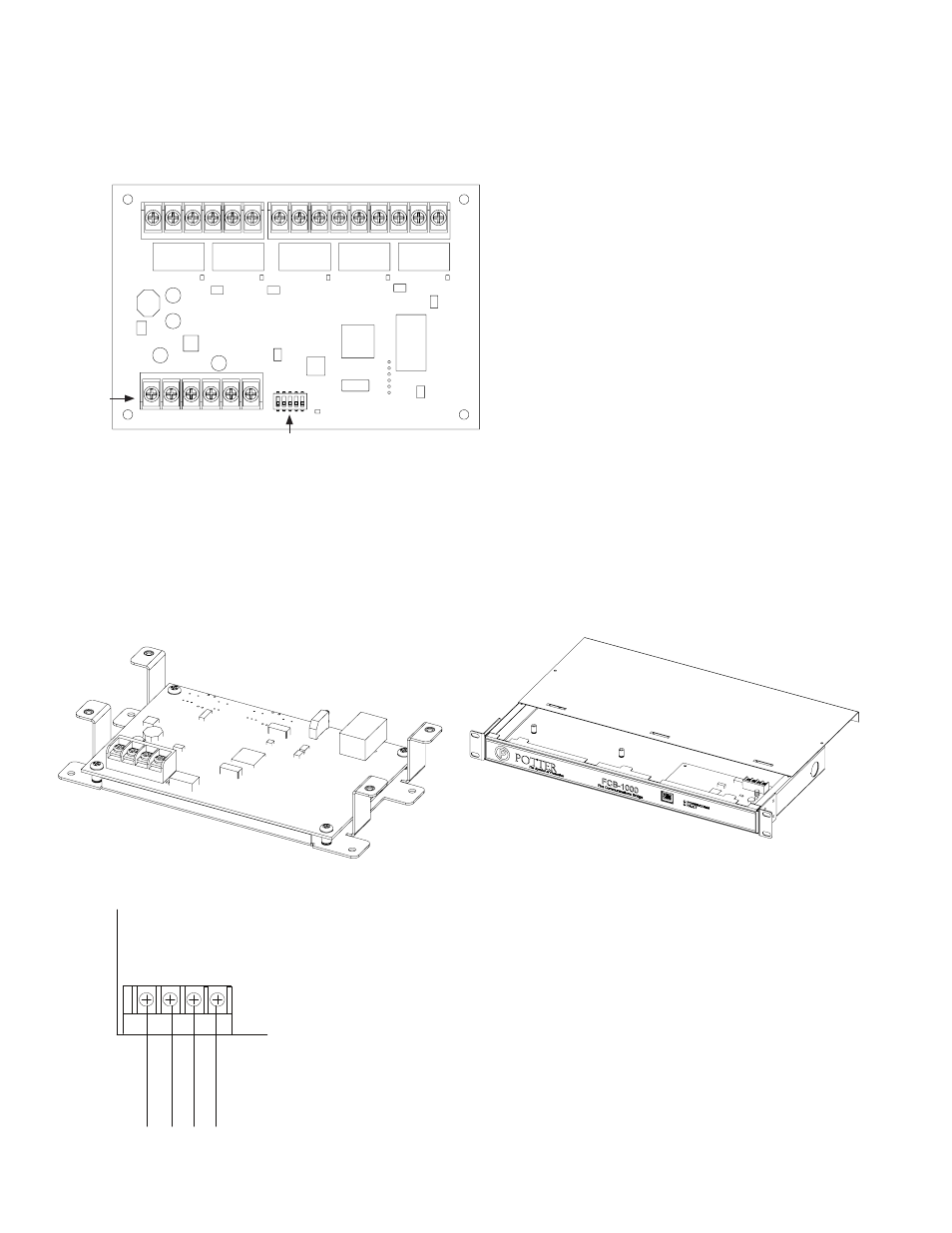
Fire Communications Bridge Installation (FCB-1000)
This panel supports one (1) Fire Communications Bridge accessory. This module provides an optional remote IP connection for IP
reporting functionality. The FCB-1000 is controlled over the 4-wire P-Link connection. This then can be mounted inside the Ae-8
or Ae-14 accessory cabinets, or the optional rack-mount kit (FCB-1000RM). The FCB-1000RM includes a standard 19 inch rack-
mount enclosure, which can then be installed directly into the IT equipment rack.
Note: The ethernet IP connection is limited to same room installation. This connection shall be limited to 20 feet and enclosed in
conduit or equivalently protected against mechanical injury.
FCB-1000 Bridge & FCB-1000RM Showing Rack Mount
Figure 44.
FCB-1000 Wiring to Control Panel Example
Figure 45.
DWG #608-13
DWG #608-14
DWG #608-21
Dip Switches
P-Link
Connections
S1
DWG #608-26
P-Link
-
+ A B
P-Link from
control panel
Example:
Powered by
control panel