Input circuits – Potter PFC-6075 User Manual
Page 110
6-104
PFC-6075 • 5403593 • Rev C • 2/13
Input Circuits
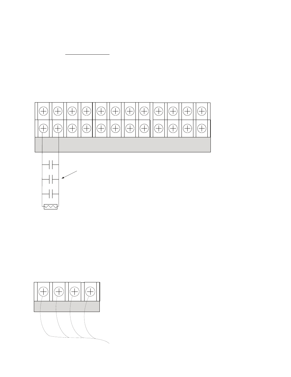
The panel is equipped with two (2) input circuits, I1 and I2, that are low voltage, power limited, and supervised. When
configured, the circuits function as dry-contact monitoring circuits.
Note: These circuits operate as Class B only. Please refer to the figure shown below.
Configuration Characteristics
Maximum allowable wire length is 10,000 feet.
•
Maximum allowable wiring resistance is 100 ohms.
•
Maximum wiring capacitance is 1 uF.
•
Maximum IDC voltage is 24 vDC, and current is 15 ma.
•
Example of PSN-1000 / PSN-1000(E) Input Circuit – Normal Open Dry Contact
Figure 143.
Notes:
The Potter part number for the listed end of line assembly is #3005013 eOL Resistor Assembly.
1.
The panel has ground fault detection on the input circuits. The impedance to ground for ground fault detection is 0 ohms.
2.
The end of line resistor is a 5.1K ohm resistor.
3.
Wiring to Control Panel
The control panel communicates with and supervises the PSN-1000/PSN-1000(e) via the main P-Link circuit. This connection
is electrically isolated from the rest of the PSN-1000/PSN-1000(e).
P-Link Wiring from Control Panel
Figure 144.
-
I1 + - NAC 1 + - NAC 5 + - NAC 3 +
-
+ A B
-
I2 + - NAC 2 + - NAC 4 + - NAC 6 +
-
+ A B
P-LINK
5.1k EOL
Potter Part #3005013
Normally Open
Dry Contact
DWG #602-26
-
+ A B
P-LINK
P-Link from
Control Panel
DWG #602-27