Repeater output – Potter PFC-6075 User Manual
Page 111
6-105
PFC-6075 • 5403593 • Rev C • 2/13
Repeater Output
The PSN-1000/PSN-1000(e) repeater output provides power which supports additional P-Link devices, including LCD Annunciators
and/or SLC Loop expanders. This is possible because the P-Link repeater output reconditions and repeats all P-Link communications.
Refer to the following figures for examples of Class A and B wiring.
Configuration Characteristics
PSN-1000 current rating is one (1) amp.
y
y
PSN-1000 voltage rating is 24 vDC.
y
y
The maximum wire length is 6,500 feet.
y
y
Wiring is fully supervised and power limited.
y
y
Maximum Wire Resistance Formula
The maximum resistance is based on the load placed on the circuit. To calculate the maximum wire resistance, use the following
formula:
(Total Annunciator Alarm Current) x (Wire Resistance) < 6 Volts
Note: Any connection to ground of 0 ohms will be annunciated as a ground fault.
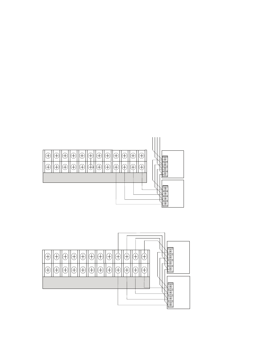
P-Link Class B (Repeater) Wiring Example
Figure 145.
P-Link Class A Wiring Example
Figure 146.
DWG #602-28
-
I1 + - NAC 1 + - NAC 5 + - NAC 3 +
-
+ A B
-
I2 + - NAC 2 + - NAC 4 + - NAC 6 +
-
+ A B
P-LINK
To the next device
-
+
A
B
Expansion
Device
-
+
A
B
Expansion
Device
- I1 + - NAC 1 + - NAC 5 + - NAC 3 +
-
+ A B
- I2 + - NAC 2 + - NAC 4 + - NAC 6 +
-
+ A B
P-LINK
-
+
A
B
Expansion
Device
-
+
A
B
Expansion
Device
DWG #602-29