Vsr-sg – Potter Releasing Systems User Manual
Page 98
98
PRINTED IN USA
PAGE 4 OF 4
MFG. #5401205 - REV G
9/09
VSR-SG
VANE TYPE WATERFLOW
ALARM SWITCH WITH RETARD
AND GLUE-IN UNION
FOR CPVC PIPE
Removal of Waterflow Switch
• To prevent accidental water damage, all control valves should be shut tight and the system completely drained before waterflow detectors are
removed or replaced.
• Turn off electrical power to the detector, then disconnect wiring.
• Loosen nuts and seperate unit from the glued-in fittings
• Gently lift the unit far enough to get your fingers under it. With your fingers, roll the vane so it will fit through the hole while continuing to lift
the waterflow detector.
• Lift detector clear of pipe.
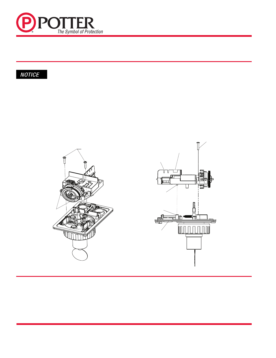
Fig. 9
Retard/Switch Assembly Replacement (See Fig. 9)
The Retard/Switch Assembly is field-replaceable without draining the system or removing the waterflow switch from the
pipe
1. Make sure the fire alarm zone or circuit connected to the waterflow switch is bypassed or otherwise taken out of service.
2. Disconnect the power source for local bell (if applicable).
3. Identify and remove all wires from the waterflow switch.
4. Remove the (2) mounting screws holding retard/switch assembly to the base. Do not remove the (2) retard housing screws.
5. Remove the retard assembly by lifting it straight up over the tripstem.
6. Install the new retard assembly. Make sure the locating pins on the retard/switch assembly fit into the locating pin bosses on the base.
7. Re-install the (2) original mounting screws.
8. Reconnect all wires. Perform a flow test and place the system back in service.
Maintenance
Inspect detectors monthly. If leaks are found, replace the detector. The VSR-SG waterflow switch should provide years of trouble-free service.
The retard and switch assembly are easily field replaceable. In the unlikely event that either component does not perform properly, please order
replacement retard switch assembly stock #1029030 (see Fig. 6). There is no maintenance required, only periodic testing and inspection.
DWG# 1190-2
BREAK OUT THIN SECTION OF COVER
WHEN WIRING BOTH SWITCHES
FROM ONE CONDUIT ENTRANCE.
DO NOT REMOVE
(2) RETARD HOUSING
SCREWS
REMOVE (2) ORIGINAL MOUNTING
SCREWS HOLDING RETARD/SWITCH
ASSEMBLY TO BASE
RETARD/SWITCH ASSEMBLY
(2) ORIGINAL MOUNTING
SCREWS
(2) LOCATING PINS
(2) LOCATING PIN
BOSSES IN BASE
BASE