Water column switch – Potter Releasing Systems User Manual
Page 103
103
MFG. #5401158 - REV D
5/08
PAGE 2 OF 3
PRINTED IN USA
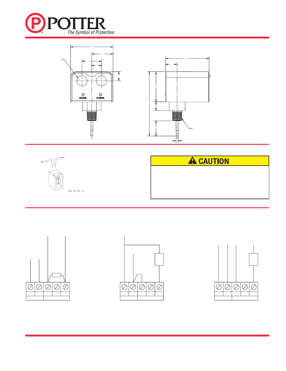
Terminal Block Connections Clamping Plate Terminal
Dimensions
N
H COM NC NO
AC POWER
OUTPUT CONTACTS
OUTPUT CONTACTS
NC
AC POWER
N
H COM
NO
EOL
LINE (HOT
)
LINE (HOT
)
SUPE
RV
ISOR
Y
+
SUPE
RV
ISOR
Y
-
NEUTRA
L
JUMPER
ALARM
WCS WIRING DIAGRAM
USING 120VAC ALARM DEVICE ONLY
WCS WIRING DIAGRAM
USING PANEL SUPERVISORY
INPUTS
DWG. #1158-5
DWG. #1158-5
WCS WIRING DIAGRAM
USING 24VDC ALARM DEVICE
DWG. #1158-5
AC POWER
N
H
NC
OUTPUT CONTACTS
COM
NO
NEUTRA
L
LINE (HOT
)
ALARM
24VDC
+
-
NEUTRAL
OUTGOING
INCOMING
1.00
3.75
5.53
2.60
.75
1.31
Ø.188
DWG. #1158-4
3.66
.84
1.68
.79
(4) Ø.886 ELECTRICAL KNOCKOUTS
FOR 1/2" CONDUIT CONNECTION
3/4" or 1/2" NPT FITTING
1.83
WCS
WATER COLUMN SWITCH
An insulated section of a single conductor should not be looped
around the terminal and serve as two seperate connections. The
wire must be severed, thereby providing supervision of the
connection in the event that the wire becomes dislodged from under
the terminal. Use 18 AWG (min.), or as required by local code.
Wire insulation rating must be at least 167°F (75°C).