Osysu-1,-2, Outside screw and yoke valve supervisory switch – Potter Releasing Systems User Manual
Page 70
70
MFG. #5400979 - REV S
5/09
PRINTED IN USA
PAGE 2 OF 4
OSYSU-1,-2
OUTSIDE SCREW AND YOKE
VALVE SUPERVISORY SWITCH
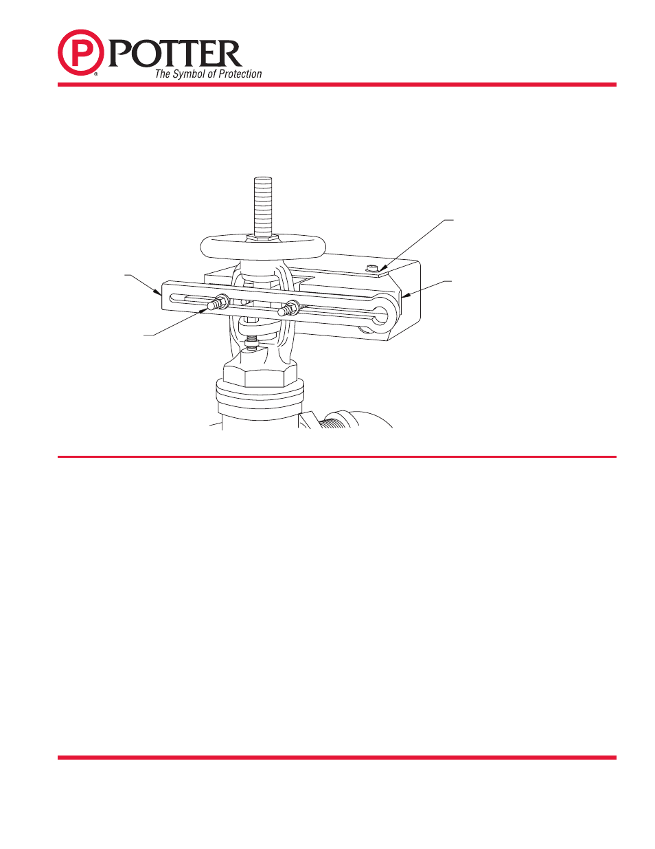
FIG. 1
SMALL VALVE INSTALLATION - 1/2" THRU 2 1/2" SIZES
and smooth the edges of the groove to prevent damage to the valve
packing and to allow the trip rod to move easily in and out of the
groove as the valve is operated.
7. Mount the OSYSU with the trip rod centered in groove.
8. Final adjustment is made by loosening 2 screws (see Fig. 1) and
sliding the OSYSU on the bracket. Adjustment is correct when
switches are not activated with the trip rod seated in the valve stem
groove and that the switches activate when the trip rod moves out
of the groove.
9. Tighten the adjustment screws and all mounting hardware. Check
to insure that the rod moves out of the groove easily and that the
switches activate within one turn when the valve is operated from
the FULL OPEN towards the CLOSED position.
NOTE: CLOSE THE VALVE FULLY TO DETERMINE THAT THE
STEM THREADS DO NOT ACTIVATE THE SWITCH. THE SWITCH
BEING ACTIVATED BY THE STEM THREADS COULD RESULT
IN A FALSE VALVE OPEN INDICATION.
SMALL VALVE INSTALLATION
1. Remove and discard "C" washer and roller from the trip rod.
2. With the valve in the FULL OPEN position, locate the OSYSU
across the valve yoke as far as possible from the valve gland, so
that the trip rod lays against the non-threaded portion of the valve
stem.
3. Loosen the locking screw that holds the trip rod in place and adjust
the rod length (see Fig. 4). When adjusted properly, the rod should
extend past the valve screw, but not so far that it contacts the clamp
bar. Tighten the locking screw to hold the trip rod in place.
NOTE: If trip rod length is excessive, loosen the locking screw
and remove the trip rod from the trip lever. Using pliers, break off
the one (1) inch long notched section (see Fig. 5). Reinstall trip rod
and repeat Step 3 procedure.
4. Mount the OSYSU loosely with the carriage bolts and clamp bar
supplied. On valves with limited clearance use J-hooks supplied
instead of the carriage bolts and clamp bar to mount the OSYSU.
5. Mark the valve stem at the center of the trip rod.
6. Remove the OSYSU. File a 1/8" deep groove centered on the mark
on the valve stem utilizing a 3/16" diameter straight file. Round
CLAMP
BAR
CARRIAGE
BOLT
DWG# 979-3
BRACKET
SLOTTED
MOUNTING
HOLES MAY BE
USED FOR FINE
ADJUSTMENT OF
SWITCH ON
BRACKET
These switches mount conveniently to most 2" to 12" OS&Y valves. They will mount on some valves as small as 1/2". J-hooks
may be required on valves with limited clearance.