Potter Releasing Systems User Manual
Page 53
53
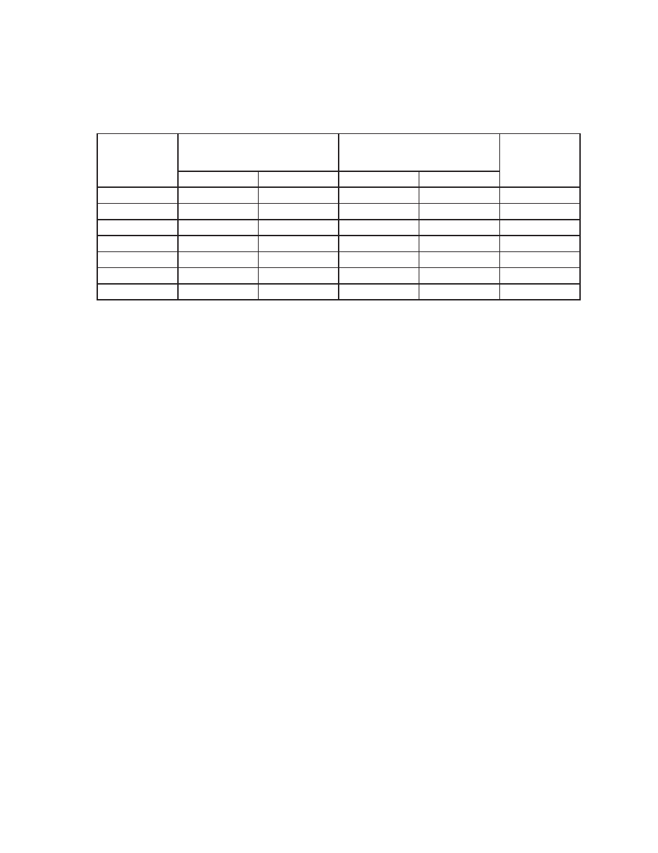
Temperature Classification for Heat-Sensing Fire Detectors NFPA 72, 2010 Table 17.6.2.1
Temperature
Classification
Temperature Rating Range
Maximum Ceiling Temperature
Color Code
°C
°F
°C
°F
low*
39-57
100-134
28
80
uncolored
ordinary
58-79
135-174
47
115
uncolored
intermediate
80-121
175-249
69
155
white
high
122-162
250-324
111
230
blue
extra high
163-204
325-399
152
305
red
very extra high
205-259
400-499
194
380
green
ultra high
260-302
500-575
249
480
orange
Note: The difference between the detectors rated temperature and the maximum ambient ceiling temperature
should be as small as possible to minimize response time.
* Intended only for installation in controlled ambient areas. Units shall be marked to indicate maximum
ambient installation termperature.
Release Systems General Information and Terminology
Single Zone Activation - Any single alarm condition will cause the release circuit to trip.
Cross Zone Activation - An alarm condition must be present on two or more zones simultaneously, before the
release circuit will be energized.
Note: Cross zoning is used to help prevent false activation of the release circuit by requiring two or more
detectors on two or more zones to alarm. It is mainly used on deluge or dry chemical systems where accidental
discharge of the extinguishing agent must be prevented.
Or on double interlock systems where a smoke or heat detector must trip and a low air switch must also trip to
indicate a loss of air pressure in the system due to an open sprinkler.
Pre-Discharge Time - The time between when the panel detects an alarm and when the release circuit is activated.
Note: The pre-discharge time is generally an adjustable timer on the release panel. It is primarily used on
dry chemical systems. The purpose of the timer is to allow the appropriate personnel time to investigate the
situation, or to allow people to evacuate the area and shut the doors before the chemical is released.
Discharge Time - The amount of time the release panel will energize the solenoid. If there is any doubt as
to the amount of time this should be programmed for, set it for continuous. This will prevent the valve from
accidently slamming shut due to a momentary drop in water pressure. In the case of a double interlock system,
it will insure that the valve will open regardless of the amount of time between when the panel detects an alarm,
and a sprinkler opens to remove pressure from the system.
Suppression systems or groups of systems shall be controlled by a single control unit that monitors the
associated initiating device(s), actuates the associated releasing device(s), and controls the associated agent
release notification appliances. If the releasing control unit is located in a protected premises having a separate
fire alarm system, it shall be monitored for alarm, supervisory, and trouble signals, but shall not be dependent on
or affected by the operation or failure of the protected premises fire alarm system.
Exception: If the configuration of multiple control units is listed for releasing device service, and if a trouble
condition or manual disconnect on either control unit causes a trouble or supervisory signal, the initiating
devices on one control unit shall be permitted to actuate releasing devices on another control unit.
NFPA 72, 2010 23.13.8 - 23.13.10 Water Flow Switch: PS10-1, PS10-2
Water flow switches on single or double interlock systems, or deluge systems must be a pressure type device.
The switch is installed in line with the intermediate chamber or alarm port. This section of piping may run to
a water motor gong or just to a drain. Under normal (no alarm) condition, there is no water or pressure in this