Pcvs-1, -2, Control valve supervisory switch – Potter Releasing Systems User Manual
Page 74
74
PAGE 2 OF 4
PCVS-1, -2
CONTROL VALVE
SUPERVISORY SWITCH
PRINTED IN USA
MFG. #5400980 - REV V
5/09
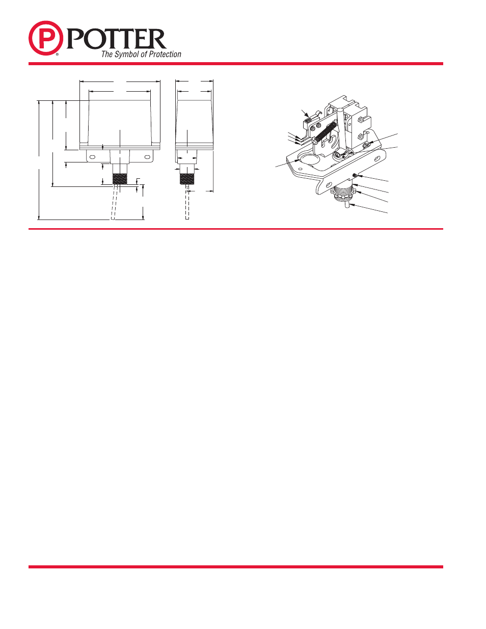
Fig. 1 Dimensions
Typical Installations On Post Indicator Valve Housings (See Figs. 3 Thru 6)
Refer to Fig. 2 for the location of parts described in the following instructions.
Note: If the sprinkler system is in service the owner or authorized representative
should be notified, before any work is done on the system, that the valve
controlling the water supply to the system may be closed for periods of time
during the installation and testing of this device, resulting in all or portions of
the system being inoperative during these periods.
If the system is not in service and valve is closed, be sure that opening the
valve will not allow any unwanted water flow due to openings in the system,
such as heads off, broken or incomplete piping, etc.
1. Position the valve to fully open (“OPEN” should appear in the window
of the housing). Partially close the valve while observing the direction
that the target assembly moves. Reopen the valve.
If the valve housing is predrilled with a 1/2" NPT for installation of a
monitoring switch, remove the 1/2" plug and fully open the valve. Make
sure that “OPEN” appears in the window of the housing. GO TO STEP
NO. 6.
2. Remove the head and target assembly (consultation with valve
manufacturer is recommended).
3. If the target assembly moved up as the valve was closed, measure the
distance from the bottom of the head to the lower part of the target
assembly that will contact the trip rod of the PCVS (see Fig. 3). This is
usually a plate or bar on the target assembly, on a side adjacent to the
“OPEN/SHUT” plates. Subtract 1/8" from the measurement.
If the target moved down as the valve was closed, measure the distance
from the bottom of the head to the upper portion of the target assembly
that will contact the trip rod of the PCVS (see Fig. 4). Add 1/8" (3,2mm)
to this measurement.
4. Mark the housing at the proper location. Using a 23/32" (18,2mm) drill
bit, drill and then tap a 1/2" NPT in the housing on the side that coincides
with the portion of the target assembly that will engage the trip rod of
the PCVS.
5. Replace the head and target assembly.
6. Loosen the socket head screw that holds the nipple in the PCVS and
remove the nipple.
7. Screw the locknut that is provided onto the nipple.
8. Screw the nipple into the 1/2" NPT hole in the valve housing - hand
tighten. Tighten the locknut against the valve housing to secure the nipple
firmly in place.
9. Insert a scale or probe thru the nipple to measure the distance from the
open end of the nipple to the target assembly. Subtract 1/2" (12,5mm)
from this measurement.
NOTE: In some cases, it may be necessary to attach an angle bracket
to the target assembly to engage the PCVS trip rod.
10. Using the special tool provided, loosen the two cover screws and remove
the cover from the PCVS.
11. Loosen the locking screw that holds the trip rod in place and adjust the
rod length, from the end of the collar to the end of the rod, using the
dimension determined in Step 9. Tighten the locking screw to hold the
rod in place.
NOTE: If trip rod length is excessive, loosen the locking screw and
remove the trip rod from the trip lever. Using pliers, break off the one
(1) inch long notched section (see Fig. 7). Reinstall trip rod and repeat
Step 11 procedure.
12. Partially close the valve (3 to 4 revolutions of the handle/hand wheel).
13. Slide the PCVS unit as far as possible onto the nipple, observing which
direction the rod will move when the valve is closed. Orient the device
to actuate the switches when the valve is open. Tighten the socket head
screw in the collar.
14. Carefully open the valve to the fully open position. As the target moves to
the open position it should engage the trip rod and actuate the switch(es).
There should be a minimum overtravel of 1/2 revolution of the handle/
hand wheel after the switch(es) actuate (a continuity meter connected
to each set of contacts is one method that could be used to determine
this).
15. Slowly close the valve. The switch must operate during the first two
revolutions of the handle/hand wheel or during 1/5 of the travel distance
of the valve control apparatus from its normal condition.
NOTE: Small adjustments of the target position may be necessary
(consultation with valve manufacturer is recommended).
16. Complete the required electrical wiring, connections and tests. The
valve should be operated through the entire cycle of fully closed and
fully open to determine the integrity of the PCVS installation and the
signaling system. Check that all electrical and mechanical connections
are secure.
17. When the installation and testing are complete, return valve to its proper
position.
18. Alternative installation for other post indicator valve housing shown in
Fig. 5 and 6.
Fig. 2 Parts
(WHITE) COM.
(WHITE) COM.
(RED) N.O.
BLACK N.C.
KNOCKOUTS FOR
ELECTRICAL
CONNECTIONS
DWG# 980-2
TRIP ROD
LOCKNUT
NIPPLE
SOCKET HEAD
SCREW
TRIP ROD
LOCKING
SCREW
GROUND SCREW
4.75
(12,1cm)
3.62
(9,2cm)
2.25
(5,7cm)
2,00
(12,1cm)
3.00
(7,6cm)
5.20
(13,2cm)
8.20
(20,8cm)
.75
(1,9cm)
.85
(2,2cm)
1.20
(3,0cm)
.12
(0,30cm)
3.12
(7,9cm)
ROD EXTENDED
ROD RETRACTED AND
BREAKAWAY SECTION
REMOVED
1.12
(2.8cm)
.85
(2,2cm)
1.56
(4,0cm)
DWG# 980-1
COVER TAMPER
SWITCH (OPTIONAL)