Rbvs, Universal ball valve switch – Potter Releasing Systems User Manual
Page 87
87
PRINTED IN USA
RBVS
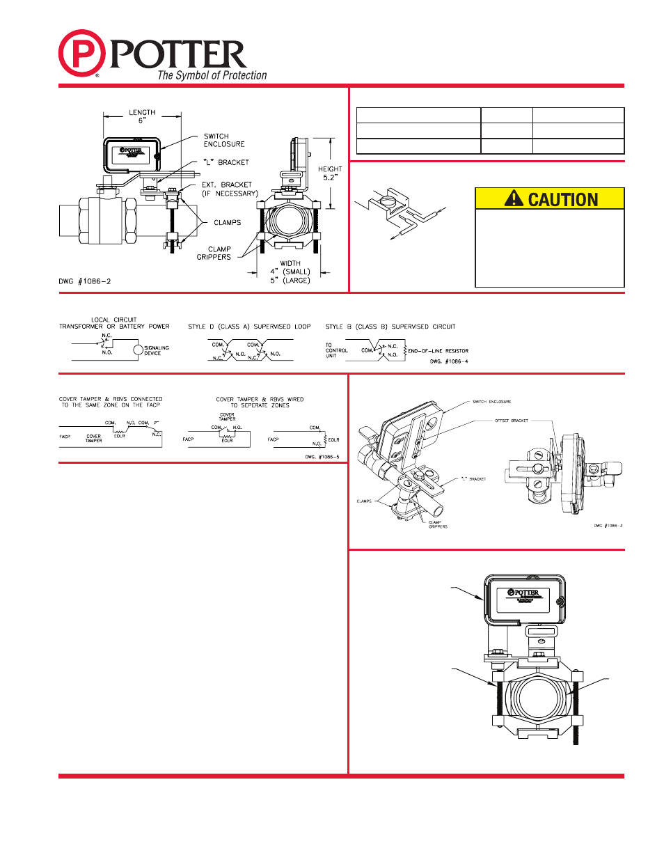
UNIVERSAL BALL
VALVE SWITCH
MFG.# 5401086 - REV V
5/09
PAGE 2 OF 2
OUTGOING
INCOM
ING
DWG# 923-3
Installation on Tee Handle (See Fig. 3)
1. Select clamps and clamping bolts based upon pipe/valve size, see Table 1.
2. Insert rubber clamp grippers into clamps, See Fig. 3.
3. Place one clamp on top of pipe/ball valve near the valve handle and
insert clamping bolts through it.
4. Place other clamp over clamping bolts from beneath the installation
and thread hex nuts onto the clamping bolts, but do not fully tighten,
(be sure hex nuts seat properly in clamp hex recesses).
5. Loosely attach "L" bracket to the "offset" bracket and "offset"
bracket to the RBVS housing.
6. Be sure ball valve is in the fully open position.
7. Slide loosely assembled RBVS switch enclosure to a position that
permits the switch button to contact the valve handle approximately
1/2" from the end of the handle. Cut and remove the plastic coating
from the ball valve handle to allow the RBVS switch button to contact
(and be activated by) the metal of the handle.
8. Tighten clamping screws alternately and ¼-20 X ¾" bolt to 30 in-lbs.
(minimum) of torque.
9. With the valve handle fully open, slide the RBVS housing down
until the switch operates plus 1/8 inch. Tighten the screws holding
the RBVS to the "offset" bracket.
10. Remove the RBVS switch enclosure cover.
11. Close and open the valve to verify operation. The actuator should
easily retract up when the valve handle is in the open position.
12. Fully open the valve.
13. Wire main switch and tamper switch (if applicable). Carefully route
tamper switch wires through strain relief channel in switch enclosure.
Fully seat the wires into the bottom of the channel. See Fig. 1.
14. Replace RBVS switch enclosure cover and securely tighten cover screw.
Fig. 3
Typical Electrical Connections
Fig. 2 Typical Mounting Diagram
Tamper Switch Connections
Switch Terminal Connections, Clamping Plate Terminal
Table 1 Clamp Sizing
Fig. 4
SOME INSTALLATIONS MAY
CAUSE INTERFERENCE
BETWEEN MOUNTING BOLT AND
OFFSET BRACKET. INSTALL BOLT
FROM BOTTOM AND TRIM AS
NEEDED TO CORRECT.
RBVS
PIPE
DWG# 1086-6
Pipe Valve/Size
Clamp
Clamping Bolts
1/2" to 3/4" (12,5 to 19mm)
Small
10-32 x 2 1/2
1" to 2" (25 to 50mm)
Large
1/4-20 x 4"
An uninsulated section of single conductor
should not be looped around the terminal
and serve as two seperate connections. The
wire must be severed, thereby providing
supervision of the connection in the event
that the wire becomes dislodged from
under the terminal.