Vsr-sg – Potter Releasing Systems User Manual
Page 96
96
PRINTED IN USA
PAGE 2 OF 4
MFG. #5401205 - REV G
9/09
VSR-SG
VANE TYPE WATERFLOW
ALARM SWITCH WITH RETARD
AND GLUE-IN UNION
FOR CPVC PIPE
Do not trim the paddle. Failure to follow these instructions may prevent the
device from operating and will void the warranty.
Do not over-tighten the union nut, hand tighten only.
Installation (see Fig. 1, 2, and 3)
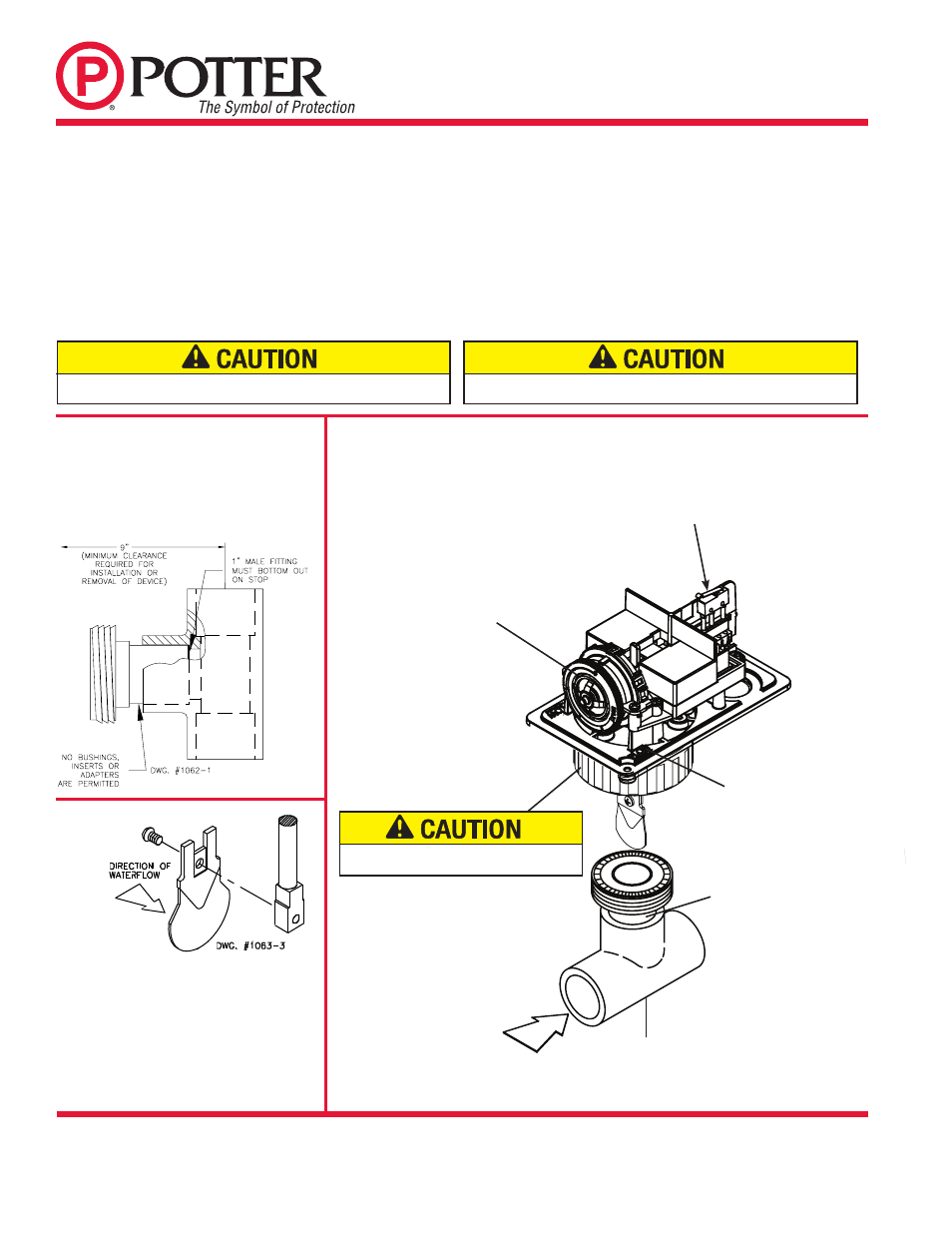
These devices may be mounted on horizontal or vertical pipe. On horizontal pipe they shall be installed on the top side of the pipe where they
will be accessible. The device should not be installed within 6" (15 cm) of a fitting which changes the direction of the waterflow or within 24"
(60 cm) of a valve or drain. The unit has a 1" male fitting for gluing into a CPVC plastic tee.
NOTE: Do not leave cover off for an extended period of time.
Loosen the union nut and separate the 1" male fitting from the VSR-SG. Glue the 1" male fitting into the TEE following the TEE manufacturer's
instructions for preparation and gluing of CPVC piping systems. (Note: The 1" male fitting must bottom out on the stop of the TEE for proper
operation of the VSR-SG. See Fig. 1.) Wait 2 to 4 hours to allow the glue to dry before attaching the VSR-SG to the 1" male fitting. Select the proper
paddle for the pipe size and type of TEE used. See Fig. 3 for instructions on how to change paddle. Verify that the o-ring is properly positioned in
its groove. Hand tighten the nut on the union after orienting the device in the appropriate direction to detect waterflow as shown in Fig. 2.
The vane must not rub the inside of the TEE or bind in any way. The stem should move freely when operated by hand.
Fig. 2
Important:
11 paddles are furnished with each unit
to accommodate the various sizes and
manufacturers of TEES. The paddles have
raised lettering that show the pipe size and
the TEE manufacturer they are to be used
with. The proper paddle must be used. The
paddle must be properly attached (see Fig. 3)
and the screw that holds the paddle must be
securely tightened.
Fig. 1
Retard Adjustment
The delay can be adjusted by rotating the retard
adjustment knob from 0 to the max setting (60-90
seconds). The time delay should be set at the
minimum required to prevent false alarms.
Glue the 1" male fitting into the TEE following
the TEE manufacturer's instructions for
preparation and gluing of CPVC piping
systems. Wait 2 to 4 hours to allow the glue
to dry before attaching the VSR-SG to the 1"
male fitting.
Fig. 3
OPTIONAL COVER TAMPER SWITCH
DWG# 1205-1A
RETARD
ADJUSTMENT
KNOB
Insure that O-ring is in O-ring groove before
installing switch.
MOUNT SO ARROW
ON BASE POINTS
IN DIRECTION OF
WATERFLOW
1" MALE FITTING
ON ALL SIZES
Do not leave cover off for extended period of time
RUN OF THE TEE
MAY BE
1”, 1 ¼”, 1
½”, or 2”
Flowing water activates device in
one direction only.