Pcvs-1, -2, Control valve supervisory switch – Potter Releasing Systems User Manual
Page 75
75
PAGE 3 OF 4
PCVS-1, -2
CONTROL VALVE
SUPERVISORY SWITCH
PRINTED IN USA
MFG. #5400980 - REV V
5/09
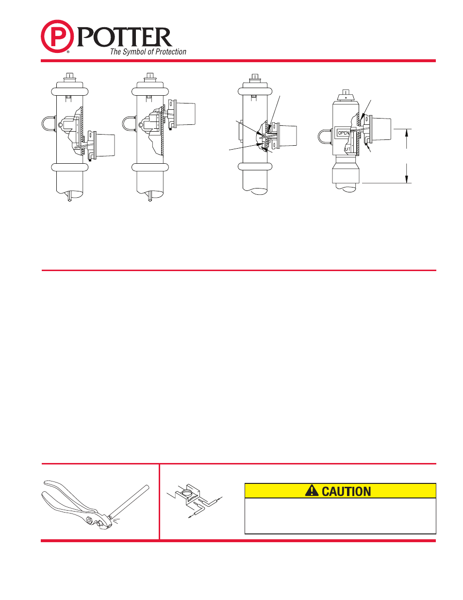
TARGET
MOVES UP
AS VALVE
IS SHUT
OPEN
UT
TAMPER
SWITCH
OPEN
UT
TAMPER
SWITCH
TARGET
MOVES
DOWN AS
VALVE IS
SHUT
DWG# 980-30
STEEL
TRIPPING
BLOCK -
REPLACES
OPEN
MARKER
SHUT
MARKER
METAL
PLATE
REPLACES
GLASS
TARGET
ASSEMBLY
TARGET
MOVES UP
AS VALVE
IS SHUT
HOOD MOVES
DOWN AS
VALVE IS SHUT
FLEXIBLE
CONDUIT
TAMPER
SWITCH
LOCKNUT
11 3/8”
(28,9cm)
Fig. 3
Fig. 4
Fig. 5
Fig. 6
Refer to Fig. 2 for location of parts described in the following
instructions:
B1. Remove the 1/2" NPT plug from the gear operator case.
B2. Loosen the set screw that holds the nipple in the PCVS and remove the nipple.
B3. Screw the locknut that is provided onto the nipple.
B4. Screw the nipple into the 1/2" NPT hole in the gear operator - hand tighten.
Tighten the locknut against the case, to secure the nipple firmly in place.
B5. Partially close the valve (3 or 4 revolutions of the hand wheel or crank).
B6. Using the special tool provided, loosen the two cover screws and
remove the cover from the PCVS.
B7. Loosen the locking screw that holds the trip rod in place. Estimate
trip rod length required and extend slightly past that point. Slide
the PCVS unit as far as possible onto the nipple, observing which
direction the rod will move when the valve is closed. Orient the
device to actuate switches when valve is open.
Note: If trip rod length is excessive, loosen the locking screw and
remove the trip rod from the trip lever. Using pliers, break off the
one (1) inch long notched section (see Fig. 7). Reinstall trip rod
and repeat Step B7 procedure.
B8. Remove device from nipple and withdraw trip rod 1/32" (0,80mm)
(this dimension is important). Tighten the locking screw to hold the
rod in place. Re-install the device on the nipple. Tighten the screw
in the collar against the nipple.
Note: In some cases it may be necessary to remove the gear box
cover to ensure correct operation (consultation with the valve
manufacturer is recommended).
B9. Carefully open the valve to its full open position, as the boss on
the gear hub moves to the open position it must engage the PCVS
trip rod and actuate the switch(es). There should be a minimum
overtravel or revolution of the crank or hand wheel after the
switch(es) actuate (a continuity meter connected to each set of
contacts is one method that could be used to determine this).
Note: Slight adjustment of gear stops may be necessary to prevent overtravel
of the trip rod (consultation with valve manufacture is recommended).
B10. Carefully close the valve. The switch(es) must operate during the first
two revolutions of the crank or hand wheel or during 1/5 of the travel
distance of the valve control apparatus from its normal condition.
B11. Complete the required electrical wiring, connections and tests. The
valve should be operated through the entire cycle of fully closed
and fully open to determine the integrity of the PCVS installation
and signaling system.
Check that all electrical and mechanical connections are secure.
B12. When the installation and testing are complete, return valve to its
proper position.
Typical Installation On A Butterfly Valve (See Figs. 9 And 10)
Fig. 7 Breaking Excessive Rod Length
Fig. 8 Switch Terminal Connections Clamping Plate Terminal
OUTGOING
INCOM
ING
DWG# 923-3
Notes:
1. Subject to the approval of the “authority having jurisdiction” the
alternate method of installation shown in Fig. 5 may be used. In
this method, one of the glass windows of the housing is replaced
with a 1/4" thick metal plate that is cut to fit in place of the glass
and drilled and tapped to receive the 1/2" NPT pipe nipple. In
some cases it may be necessary to attach an angle bracket to the
target assembly to engage the PCVS trip rod.
DWG# 980-13
2. If the target is stationary and a hood arrangement is used, such as
is shown in Fig. 6, the hood must be drilled with a 23/32" drill and
tapped with a 1/2" NPT. The center line of this hole should be 1/8"
below the portion of target assembly that strikes the PCVS trip
rod. The 11 3/8" dimension shown is for a Clow Valve. Flexible
conduit must be used for this type of installation.
An uninsulated section of a single conductor should not be looped around the
terminal and serve as two separate connections. The wire must be severed,
thereby providing supervision of the connection in the event that the wire
becomes dislodged from under the terminal.