Rbvs, Universal ball valve switch – Potter Releasing Systems User Manual
Page 86
86
PRINTED IN USA
RBVS
UNIVERSAL BALL
VALVE SWITCH
MFG.# 5401086 - REV V
5/09
PAGE 1 OF 2
US Patent No. 6,945,509
General
The Model RBVS is designed to monitor the fully open position of a ball valve
installed in a sprinkler system. The unit will fit on most ball valves installed on
back-flow-preventers and alarm trim lines of dry, alarm, and deluge sprinkler
valves. The switch operates if the ball valve handle is moved from the open
position. However, the switch does not track the position of the handle or ball.
When the ball valve handle is in the open position, a spring-loaded switch button
will contact the valve handle. When the handle is moved from the open position,
this switch button extends to the tripped position, and the RBVS contacts change
state, thereby opening or closing a circuit. A cover tamper switch is available and
is activated by the removal of the RBVS housing cover. If an attempt is made
to remove the RBVS by the removal of the mounting brackets, the unit will be
set into the tripped mode by this action.
The RBVS can be mounted to the hex portion of the ball valve or back-flow-
preventer or to the adjoining pipe via two clamps. The RBVS is shipped with two
sets of mounting clamps to accommodate various pipe and valve sizes, refer to
Table 1. An "L" shaped and offset bracket for mounting the switch enclosure and
an extension bracket add to the mounting flexibility of the RBVS. See "Typical
Mounting Diagram" and "Installation and Operation" on following page.
Testing
The RBVS and its associated protective monitoring system should be tested
in accordance with applicable NFPA codes and standards and/or the authority
having jurisdiction (manufacturer recommends quarterly or more frequently).
UL and cUL Listed, FM, CSFM Approved
Dimensions:
(including mounting clamps)
Large Clamps: 6" L x 5" W x 5.2" H
15,2 cm L x 12,7 cm W x 13,2 cm H
Small Clamps: 6" L x 4" W x 5.2" H
15,2 cm L x 10,2 cm W x 13,2 cm H
Weight:
With Large Clamps: 13.6 oz. (386,9 g.)
With Small Clamps: 11.0 oz. (311,2 g.)
Enclosure: Non-Corrosive Composite Material
Environmental Limitations:
• NEMA 4 rated enclosure when proper electrical
fittings are used. (IP67)
• Temperature range: -40°F to 150°F (-40°C to 65°C)
• Not for use in hazardous locations
Housing Cover Tamper: Activated by housing cover removal
(Stock No. 1000035 only)
Contact Ratings:
SPDT Contacts:
10A at 125/250 VAC
2A at 30 VDC
SPDT Cover Tamper: 3A at 250 VAC
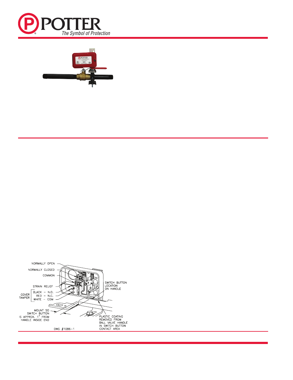
Fig.1 Internal Components
Potter Electric Signal Company, LLC • St. Louis, MO • Phone: 866-956-0988/Canada 888-882-1833
• www.pottersignal.com
RBVS Stock No. 1000040 (w/o Cover Tamper)
RBVS-T Stock No. 1000035 (w/Cover Tamper)
Optional Cover Tamper Kit Stock No. 0090201
Installation On Lever Handle (See Fig. 2)
1. Select clamps and clamping bolts based upon pipe/valve size, see Table 1.
2. Insert rubber clamp grippers into clamps, see Fig. 2.
3. Place one clamp on top of pipe/ball valve near the valve handle and
insert clamping bolts through it.
4. Place other clamp over clamping bolts from beneath the installation and
thread hex nuts onto the clamping bolts, but do not fully tighten, (be sure
hex nuts seat properly in clamp hex recesses). (NOTE: Some installations
may require one of the mounting bolts to be inserted from the bottom of
the brackets and then trimmed to allow the extension bracket to clear.
See Fig. 4)
5. Attach extension bracket (if necessary to use for positioning) to top clamp
using ¼-20 X ¾" Hex bolt and washer, but do not fully tighten.
6. Attach "L" bracket (RBVS switch enclosure is loosely attached to "L"
bracket) to extension bracket using ¼-20 X ¾" Hex bolt and washer, but
do not fully tighten.
7. Be sure ball valve is in the fully open position.
8. Slide loosely assembled RBVS switch enclosure to a position that permits
the switch button to contact the valve handle approximately 1" from its
inside end. See Fig. 1 for approximate location. Cut and remove the plastic
coating from the ball valve handle to allow the RBVS switch button to
contact (and be activated by) the metal of the handle.
9. Tighten clamping screws alternately to an eventual 30 in-lbs. (minimum)
of torque.
10. Maintain position of switch enclosure over valve handle and secure bolt
that holds the extension bracket to the clamping assembly. It may be
necessary to close valve to access this bolt.
11. Position "L" bracket so that it contacts the back edge of the valve handle, and
secure its bolt. It may be necessary to close valve to access this bolt.
12. With the actuator fully retracted, position RBVS switch enclosure to
contact the valve handle squarely, see Fig. 1.
13. With RBVS switch enclosure held squarely in contact with valve handle,
securely tighten the two tamper resistant screws on the backside of the
enclosure.
14. Close and open the valve to verify operation. The actuator should easily
retract when the valve handle is in the open position.
15. Fully open the valve.
16. Remove the cover and wire main switch and tamper switch if applicable.
Carefully route tamper switch wires through strain relief channel in switch
enclosure. Fully seat the wires into the bottom of the channel. See Fig. 1.
17. Replace RBVS switch enclosure cover and securely tighten cover screw.