Vsr-s, Vane type waterflow alarm switch with retard, For small pipe – Potter Releasing Systems User Manual
Page 93: Fig. 7 cover tamper switch wiring
93
PRINTED IN USA
MFG. #5401206 - REV G
12/08
VSR-S
VANE TYPE WATERFLOW
ALARM SWITCH WITH RETARD
FOR SMALL PIPE
PAGE 2 OF 3
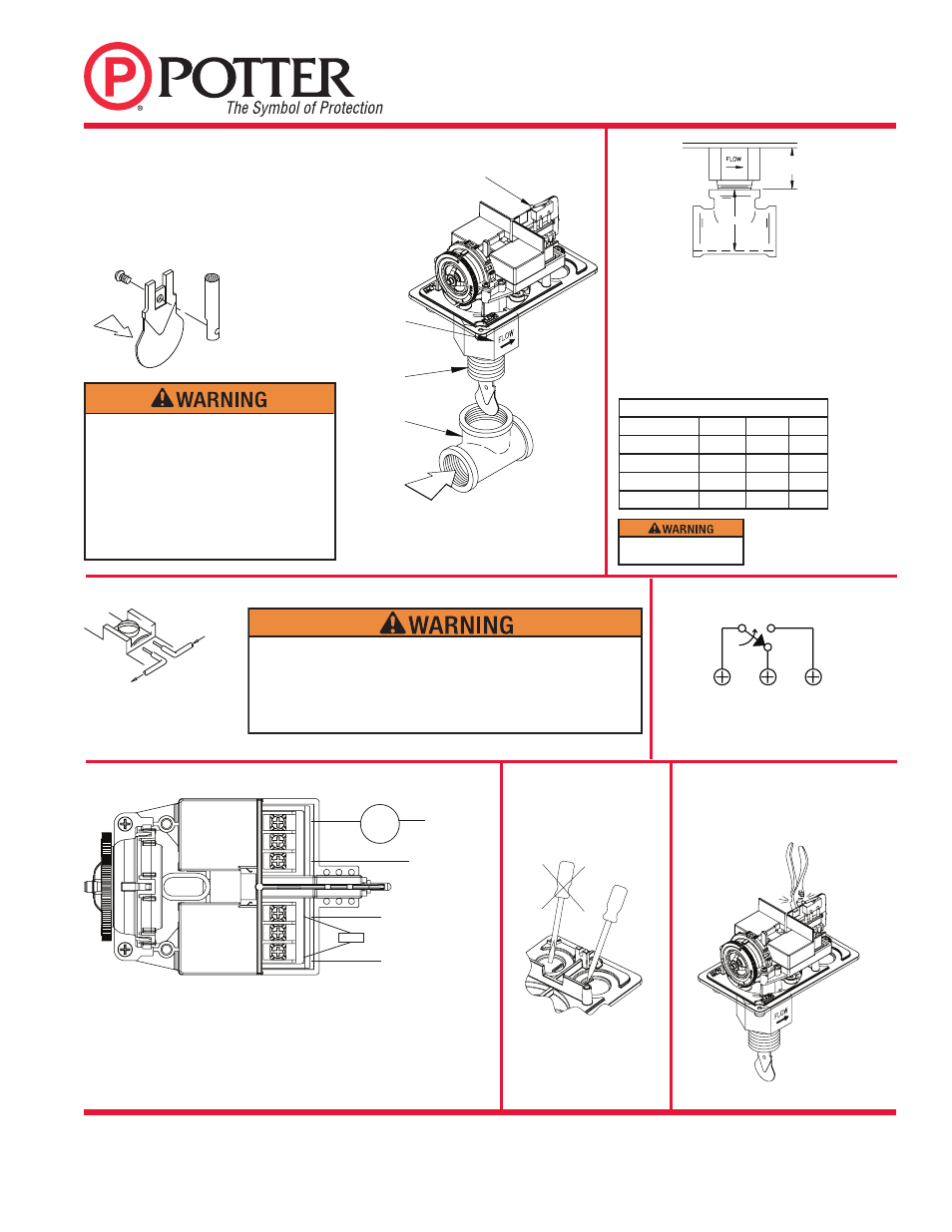
COVER TAMPER SWITCH
MOUNT SO
ARROW ON
BUSHING POINTS
IN DIRECTION OF
WATERFLOW
1” NPT
THREADED
FITTING ON
ALL SIZES
RUN OF THE TEE
MAY BE
THREADED OR
SWEAT PIPE
DIRECTION OF
WATERFLOW
DWG# 802-30A
Fig. 1
Fig. 2
Notes:
1. The Model VSR-S has two switches, one can be used to operate a
central station, proprietary or remote signaling unit, while the other
is used to operate a local audible or visual annunciator.
2. For supervised circuits see “Switch Terminal Connections” drawing
and caution note (Fig. 3).
Retard Adjustment
The time delay is factory set at 30 ± 10 seconds.
The delay can be adjusted by rotating the retard
adjustment knob from 0 to the max setting (60-90
seconds). The time delay should be set at the
minimum required to prevent false alarms.
Fig. 3 Switch Terminal Connections Clamping Plate Terminal
OUTGOING
INCOM
ING
DWG# 923-3
To remove knockouts:
Place screwdriver at edge of
knockouts, not in the center.
Screw the device into the tee fitting as shown.
Care must be taken to properly orient the
device for the direction of waterflow. On sweat
tees, no threaded bushings, inserts, or adapters
are permitted, unless they comply with the
dimensions listed in the chart below.
Important - The depth to the inside bottom of
the tee should have the following dimensions:
DIRECTION OF
WATER FLOW
DWG# 737-31
Shown with optional Cover Tamper Switch Kit.
DWG 1146-4
DWG# 8810018-2
C
(WHT)
N.O.
(RED)
N.C.
(BLK)
Fig. 7 Cover Tamper Switch Wiring
(Shown with cover in place)
DO NOT LEAVE COVER OFF FOR EXTENDED PERIOD OF TIME
4,3MM
(1 11/16”)
APPROX.
DEPTH
DWG# 735-33
Approximate Depth Requirement
Tee Size
Threaded
Sweat
CPVC
1" x 1" x 1"
2 1/16"
1 3/4"
2 7/16"
1 1/4" x 1 1/4" x 1"
2 7/16"
2 7/16"
N/A
1 1/2" x 1 1/2" x 1"
2 11/16"
2 1/4"
N/A
2" x 2" x 1"
3 3/16"
2 3/4"
N/A
DWG# 1146-3A
POSITIVE DC OR
HOT AC
NEGATIVE DC OR
NEUTRAL AC
WATERFLOW ZONE ON
FIRE PANEL
BELL
EOLR
COM
NC
NO
NO
NC
COM
Break out thin section of cover when wiring
both switches from one conduit entrance.
DWG# 1206-2
An uninsulated section of a single conductor should not be looped
around the terminal and serve as two separate connections. The wire
must be severed, thereby providing supervision of the connection in
the event that the wire become dislodged from under the terminal.
Failure to sever the wire may render the device inoperable risking
severe property damage and loss of life.
Fig. 4 Typical Electrical Connections
Fig. 5
Fig. 6
There are 12 paddles furnished with each unit.
One for each size of threaded, sweat or plastic
TEE as described in Fig. 2. These paddles have
raised lettering that shows the pipe size and type
of TEE that they are to be used with. The proper
paddle must be used. The paddle must be properly
attached (see drawing) and the screw that holds
the paddle must be securely tightened.
Do not use more than three
wraps of teflon tape.