Vsr-st, Vane type waterflow alarm switch with retard, For small pipe – Potter Releasing Systems User Manual
Page 100: Fig. 2, Fig. 1, Fig. 3 cover tamper switch, Fig. 5 typical electrical connections
100
FOR SMALL PIPE
PRINTED IN USA
MFG. #5401204- REV F
12/08
PAGE 2 OF 3
VSR-ST
VANE TYPE WATERFLOW
ALARM SWITCH WITH RETARD
DWG# 1146-3A
DWG# 8810018-2
C
(WHT)
N.O.
(RED)
N.C.
(BLK)
An uninsulated section of a single conductor should not be looped around the terminal and serve as
two separate connections. The wire must be severed, thereby providing supervision of the connection
in the event that the wire becomes dislodged from under the terminal.
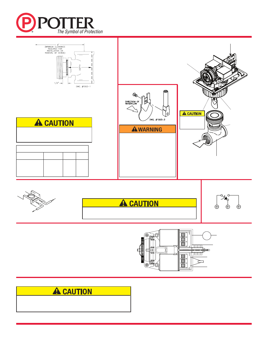
Fig. 2
There are 12 paddles furnished with
each unit. One for each size of threaded,
sweat or plastic TEE as described in Fig.
1. The paddles have raised lettering that
show the pipe size and type of TEE that
they are to be used with. The proper
paddle must be used. The paddle must
be properly attached (see Fig. 3) and
the screw that holds the paddle must be
securely tightened.
Notes:
1. The model VSR-ST has two switches, one can be used to operate a
central station, proprietary or remote signaling unit, while the other
is used to operate a local audible or visual annunciator.
2. For supervised circuits see “Switch Terminal Connections”
drawing and CAUTION note (Fig. 4).
Fig. 4 Switch Terminal Connections Clamping Plate Terminal
OUTGOING
INCOM
ING
DWG# 923-3
Approximate Depth Requirement
Tee Size
Threaded
Sweat
CPVC
1" X 1" X 1"
2-1/16"
1-3/4"
2-7/16"
1-1/4" X 1-1/4" X 1" 2-7/16"
2-7/16"
N/a
1-1/2" X 1-1/2" X 1" 2-11/16"
2-1/4"
N/a
2" X 2" X1"
3-3/16"
2-3/4"
N/a
Fig. 1
Screw the fitting into the TEE fitting as shown.
On sweat TEE's, no threaded bushings, inserts or adapters are
permitted unless they comply with the dimensions listed in the
chart below.
Important - the depth to the inside bottom of the TEE should
have the following dimensions:
Fig. 3
Cover Tamper Switch
(Shown with cover in place)
Shown with optional Cover Tamper Switch.
Retard Adjustment:
The delay can be adjusted by rotating
the retard adjustment knob from 0
to the max setting (60-90 seconds).
The time delay should be set at the
minimum required to prevent false
alarms.
Do not leave cover off for an
extended period of time.
Fig. 5 Typical Electrical Connections
DWG# 1204-1A
RETARD
ADJUSTMENT
KNOB
MOUNT SO ARROW
ON BASE POINTS
IN DIRECTION OF
WATERFLOW
1" NPT MALE FITTING
ON ALL SIZES
RUN OF THE TEE
MAY BE 1" , 1 1/4", 1
1/2", OR 2"
INSURE THAT O-RING
IS IN O-RING GROOVE
BEFORE INSTALLING
SWITCH.
To prevent leakage apply teflon tape sealant to the
1" NPT male fitting only. Do not use any other type
of lubricant or sealant.
POSITIVE DC
OR HOT AC
NEGATIVE DC OR
NEUTRAL AC
WATERFLOW ZONE
ON FIRE PANEL
BELL
EOLR
NO NC COM
COM NC NO
Waterflow switches that are monitoring wet pipe sprinkler systems shall not
be used as the sole initiating device to discharge AFFF, deluge, or chemical
suppression systems. Waterflow switches used for this application may result in
unintended discharges caused by surges, trapped air, or short retard times.