Flintec DAS 72.1 User Manual
Page 22
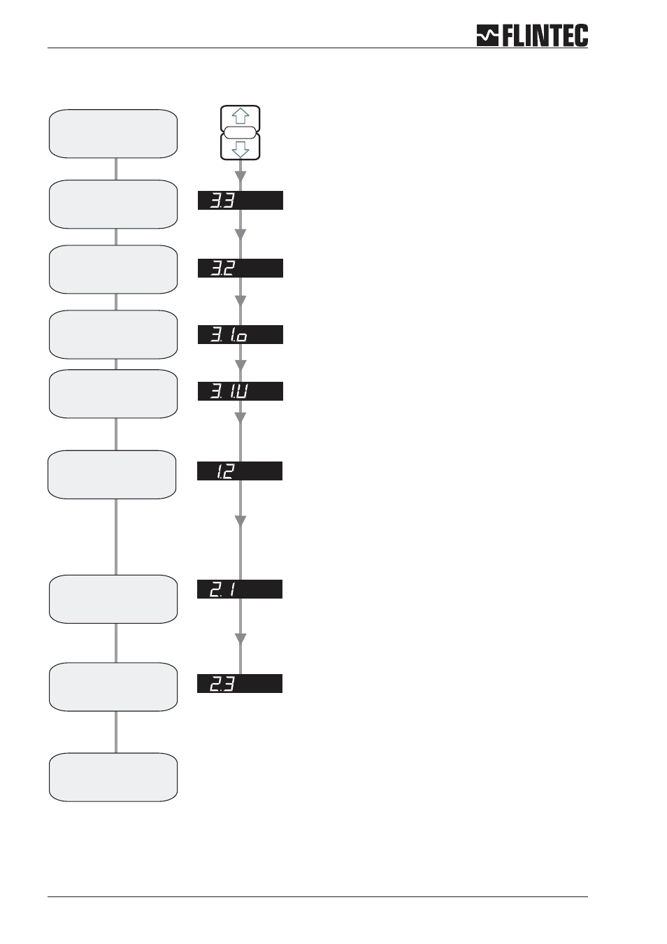
Flowchart Example 3
Page 22
Manual DAS 72.1
SET UP
SET THE DISPLAY STEP SIZE. (1, 2, 5, 10, 20, 50, 100, 200, 500)
Use the UP or DOWN key to set the required display step size.
SET THE DISPLAY OVER RANGE LIMIT. (MAX. VALUE +99999)
Use the UP/DOWN & MOVE RIGHT keys to set the maximum display value
above which the display shows over range
(all dashes in the top of the display).
SET THE DISPLAY UNDER RANGE LIMIT. (MIN. VALUE -99999)
Use the UP/DOWN & MOVE RIGHT keys to set the minimum display value
below which the display shows under range
(all dashes in the bottom of the display).
SET THE DECIMAL POINT POSITION (0, 0.0, 0.00, 0.000, 0.0000)
Use the UP or DOWN key to set the required decimal point position.
Choose 0.0
SET THE SPAN CALIBRATION VALUE.
Use the UP/DOWN & MOVE RIGHT keys to set the display value equivalent to
the load cell summary nominal load, e.g. 3,000 kg.
Choose 3000.0 for load cell summary nominal load 3000 kg
CALIBRATE THE SPAN FROM mV/V LOAD CELL SENSITIVITIES
Use the UP/DOWN & MOVE RIGHT keys to set the mV/V reading equivalent
to the span calibration value set in section 2.1.
Choose 2.0000 Sensitivity for summary nominal load 3000 kg
Choose Filter type IIR (menu 4.2), Low Pass Filter 6 ... 8 (menu 4.1) and
wait for ‘No Motion’ in the calibration routine.
Note:
Enter the
Set-up menu
Set the
step size
display
Set the Display
Upper Limit
(Overload)
Set the decimal
point position
Set the Display value
equal to
mV/V sensitivity
Set mV/V equivalent
to
Span Calibration Value
Calibration
completed
Set the Display
Lower Limit
Calibrate the
Zero point
CALIBRATE THE ZERO POINT IN mV/V.
Use the UP/DOWN & MOVE RIGHT keys to set the load cell summary mV/V
value, e.g. 0.000 mV/V.
1. Press the UP or DOWN key for more than
3 seconds to enter the Set-up Menu
2. Press the recessed enable switch