B.4 examples 17 – Flintec DAS 72.1 User Manual
Page 17
B.4
EXAMPLES
B.4.1 Example 1, calibration procedure using weights
Manual DAS 72.1
Page 17
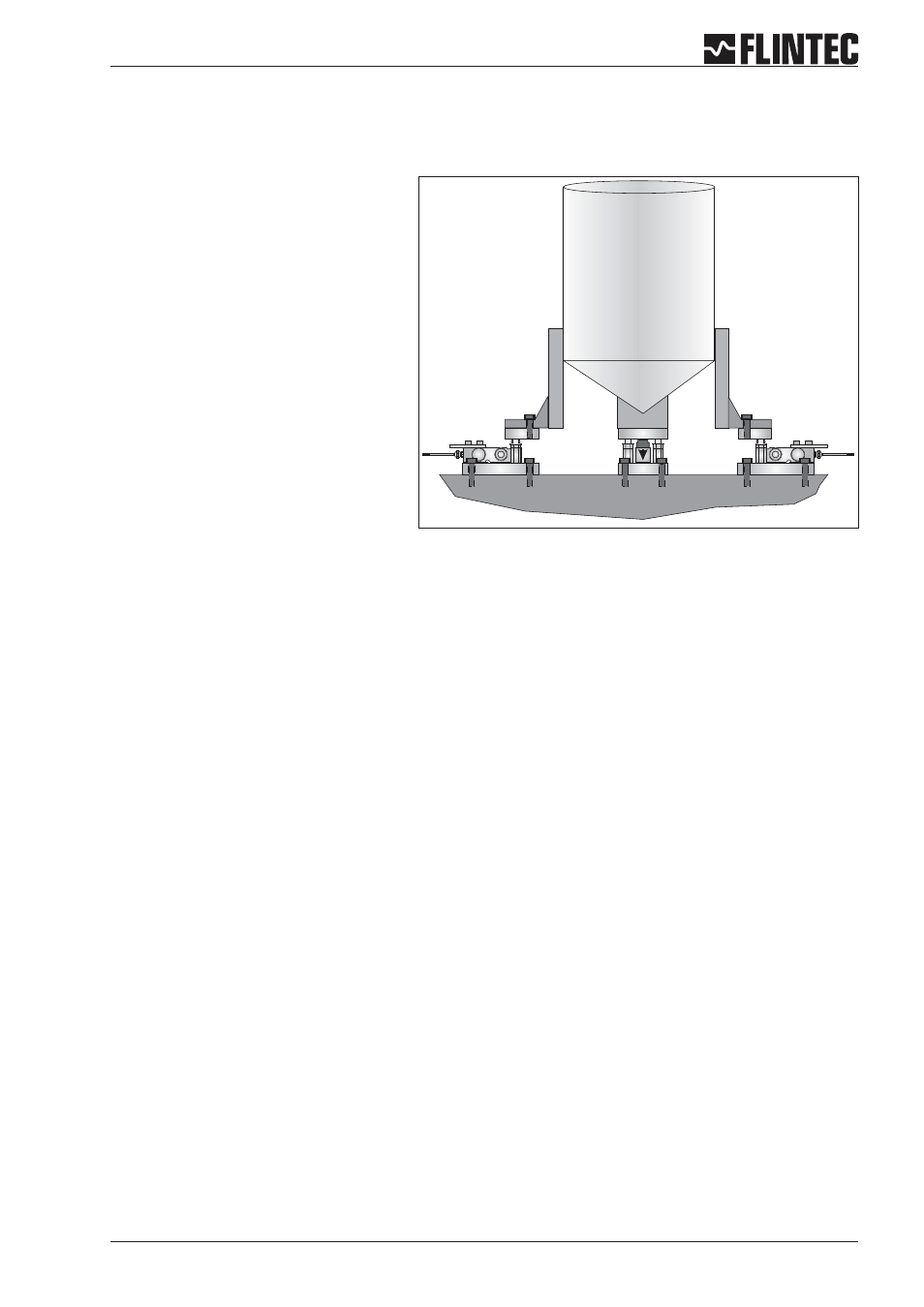
3 Leg tank or silo fitted with 3 off 1000 kg
@ 2 mV/V load cells.
Dead load 600 kg.
Live range 2000 kg in 0.5 kg steps.
It is assumed that the load cell system is
connected to the DAS72.1 and the power
is on. The maximum and minimum display
values, display increment size and decimal
point position should be defined prior to
carrying out the calibration (See Menu 3).
For this example the display maximum is
defined as 2100.0, the display minimum is
-200.0, the display step size is 0.5 kg.
Remember that all parameters under
sections 1.1 - 1.3, 2.1 - 2.3 and 3.1 - 3.3 can only be accessed or changed after the Recessed Enable
Switch has been pressed.
a
Go to Menu 1.2 and using the UP/DOWN and RIGHT keys set the display to read 0000.0. Make sure that the
weighing system is empty or at the point where you want the display to read zero. Press the 0 [Enter] key.
This defines the actual zero calibration point.
b
Go to Menu 2.1 and using the UP/DOWN and RIGHT keys set the display to read the value of the calibration
weight(s) applied. For this example if the calibration load applied is 750 kg set the display to read 750.0.
Press the 0 [Enter] key. This defines the calibration weight.
c
Go to Menu 2.2. Apply the calibration weight(s) to the weighing system. Press the 0 [Enter] key. The display
will show the actual input signal in mV/V. Press the 0 [Enter] key. This defines the actual span calibration
point. The display will show 2.2. Press the right arrow key twice and the DAS will be back in weighing mode.
Calibration is now completed.