Flintec DAS 72.1 User Manual
Page 18
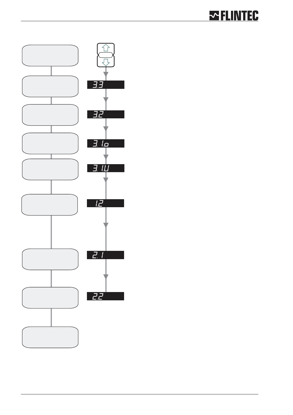
Flowchart Example 1
Page 18
Manual DAS 72.1
SET UP
SET THE DISPLAY STEP SIZE. (1, 2, 5, 10, 20, 50, 100, 200, 500)
Use the UP or DOWN key to set the required display step size.
1. Press the UP or DOWN key for more than
3 seconds to enter the Set-up Menu
2. Press the recessed enable switch
SET THE DISPLAY OVER RANGE LIMIT. (MAX. VALUE +99999)
Use the UP/DOWN & MOVE RIGHT keys to set the maximum display value
above which the display shows over range
(all dashes in the top of the display).
SET THE DISPLAY UNDER RANGE LIMIT. (MIN. VALUE -99999)
Use the UP/DOWN & MOVE RIGHT keys to set the minimum display value
below which the display shows under range
(all dashes in the bottom of the display).
SET THE DECIMAL POINT POSITION (0, 0.0, 0.00, 0.000, 0.0000)
Use the UP or DOWN key to set the required decimal point position.
Choose 0.0
SET THE SPAN CALIBRATION VALUE.
Use the UP/DOWN & MOVE RIGHT keys to set the display value equivalent
to the calibration weight, e.g. 750 kg.
CALIBRATE THE SPAN. (CONVENTIONAL WEIGHING SYSTEM)
Display shows the actual input signal in mV/V. Apply test weights equivalent
to the calibration value set in section 2.1.
Press the Enter key to store the new Span value
Choose Filter type IIR (menu 4.2), Low Pass Filter 6 ... 8 (menu 4.1)
and wait for ‘No Motion’ in the calibration routine.
Note:
Enter the
Set-up menu
Set the
step size
display
Set the Display
Upper Limit
(Overload)
Set the decimal
point position
Set the Display value
equal to the
Calibration weight
Calibrate
the Span
Calibration
completed
Set the Display
Lower Limit
Calibrate the
Zero point
CALIBRATE THE ZERO POINT. (CONVENTIONAL WEIGHING SYSTEM)
Display shows the actual input signal in mV/V.